Most projects must use energy from a power supply.
First, we use a battery. It is good for Portable device. But it runs out of power. Even rechargeable batteries, also not comfortably.
You should use An unregulated power supply. It is cheap and easy by making yourself.
And, the unregulated power supply circuit design skill is great in electronics learning.
What is an unregulated power supply
Some called these power supplies that AC adapter. Both change a high AC voltage from a wall socket into DC low voltage for any electrical appliances.
For example, a DC 12V pump, 12V LED light bulbs, Grandpa’s FM radio, etc.
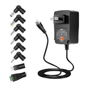
For example a great AC adapter.
Cr: Belker
Next, I called short these that “loads”.
Let’s design it
We want the power supply that having these features.
- A constant voltage
- Smoothing current
- High currents
- High voltages
- Charge Rechargeable batteries
- Small to fit space
- Cheap
Choose a power supply to fit
Your load will run well. If you choose the suitable voltage and electric current.
Load’s voltage—Important, we need to set the output voltage as load want.
Electric current ranges—-check load how many the electric current rate?
We can put them in 3 groups as follows.
1. Low current—usually 150mA or 500mA
2. Medium current—usually 1A to 2A
3. High current—3A, 6A, 10A, and Higher.
If you cannot imagine.
For example, we have a 12V LED light bulb. It uses the only 20mA. So, we build power supply of 12V@150mA. It can run very well. Also, works if use 1A. But the big and expensive. Do you choose this?
Another one…
Often friend builds the 12V@2A power supply for a Car FM Audio Player. It is a great sound.
Some called these power supply that AC adapter. It is good for a normal load. If you use other specific loads. For example, digital circuits, Preamplifiers, etc. You need to use a Regulated power supply.
Which now I will explain to you learn the unregulated power supply first.
The main structure
See the main structure of an Unregulated power supply. It consists of 3 sections.
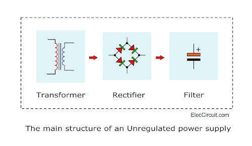
We will learn its outline of 3 stages. Which can be combined to give the best and cheap power supply for you.
The power transformer
AC House voltage
You know that the power outlets have a high AC voltage. Each Country is a different voltage.
For example,
In North America, South America, Japan, and some other nations of 117 volts. European of 230 volts, And some country of 220 volts.
As the high main AC voltage is long. So, from this point onward, I have called “AC Mains” follows Mr.Colin Mitchell.
Ohh! Too high voltage. It can’t use with any low voltage appliances.
But not worry, the power transformer can help us. How?
It will pass the AC mains flows to reduce the voltage down.
And, with this feature, we also called “step down transformer“.
The transformers have many features. Which we need to know as following.
- A transformer does not give a direct current(DC). It supplies only alternating current (AC).
- The primary and secondary windings are usually marked on a transformer. You must know “which is which”.
- If you have two transformers. Both voltages are the same(V). But they are different wattage. More wattage(VA), more electric current(V).
Types of secondary windings
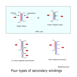
These are the four most common types of secondary windings. As following.
- Single secondary windings output.
- Center-tapped secondary output.
- 2 or more separated secondaries
- Multi-tapped secondary winding
We often use both types of single output and the center-tapped output.
Others types, sometimes we may use a type of more separated and multi-tapped secondary.
The rectifier Diode
A diode is a good rectifier circuit. It works only a correct connecting. A Diode is like a one-way water valve.
In the diagram
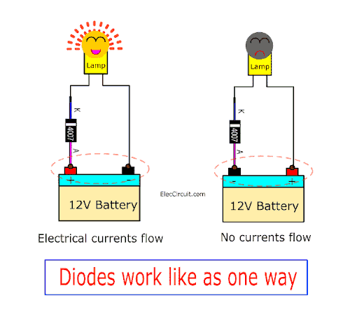
If the battery is correct polarity. The electrical current can flow a lamp light up.
But, we turn the battery polarity. The electrical current cannot flow, no light.
How diode rectifier works
I am a little worry. How to explain you clear in this. It is better if you see a lot of block diagram of the circuit. A rectifier of unregulated power supply has 3 types as follows.
- Half wave rectifier with one diode
- Full wave rectifier using center tap transformer with two diodes
- Full wave rectifier bridge rectifier with 4 diodes
The Half wave rectifier
This is the simplest rectifier with only one diode. It passes only the positive of AC voltage to the output.
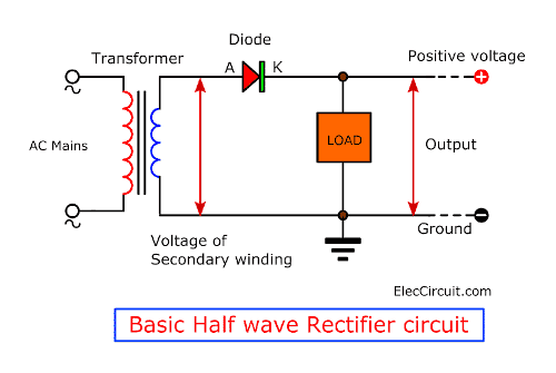
See in this circuit is basic half rectifier. It is good at charging a battery. Some called an Unfiltered DC supply. But it is not great for most electronics projects.
Because it uses only half the energy. And, the transformer is heat-up too.
Slow first…
Even you do not use it. But it is the step of great learning.
Back to see the waveform of the transformer. At the secondary, AC voltage is lower than the AC main. And the opposite phase, too.
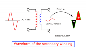
During this period of time. The top of a secondary winding waveform is positive. And, the bottom is negative.
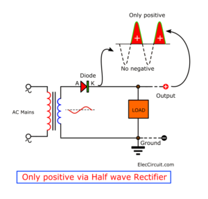
In the block diagram.
During this period, the diode runs and in the only the positive side. And, the output has only a positive waveform.
Some called “Pulsed or Pulsating DC (PDC)”. This is a frequency of 50Hz or 60Hz.
We see close up the waveform in a graph.
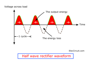
In one cycle has both positive and negative. And, every cycle is the same. The positive is output energy. But, the negative can’t via a diode. So, it is energy loss.
Everything wants to change to be better.
Like us, want full energy from the full cycle. See more below.
Also, here are a couple of related posts you should read, too:
What is more?
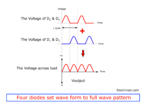
The full wave rectifier
A center-tapped transformer and two diodes set a full-wave rectifier circuit. It works as 2 separate in 1/2 wave circuit. When the top diode runs, the bottom diode stop. And both diodes work alternately. To pass only positive voltage to the output too.
I know my text is not clear. Do you understand?
Read below.
Back to see the secondary of a center-tapped transformer.
How does watch its waveform?
It is easy with 2 channel oscilloscope.
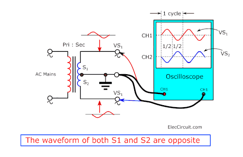
See in the figure.
The CT is the ground. Then measure the signal at VS1 and VS1. We will see that.
- Both secondary windings, S1 and S2 are the same. But the opposite.
- Half and half is one cycle of the waveform.
Try with two rectifier diodes
And, we need to add two resistors as a load. Then, watch a signal across both resistors are VR1 and VR2.
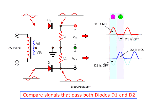
See in Figure, we know.
- Both diodes D1 and D2 will run. When the signal is positive only.
- So, the signal of VR1 and VR2 is positive only.
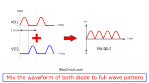
Next, On the left is the waveform. Focus at the 1 cycle that has 1 and 2. It is a half circuit each other.
Imagine If you mix both VR1 and VR2. With connecting both cathodes
of both diodes is the same as above the basic circuit.
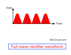
It will be a thing we want. Both signals mixed great. In patterns of the full-wave rectifier with center-tapped transformer. See in Figure. Some called Pulsating DC.
Even this circuit is a full-wave rectifier. But there is still a disadvantage:
We need to use a center-tapped transformer. This may be difficult to find and the Diode patch receives a high current. We always have better options.
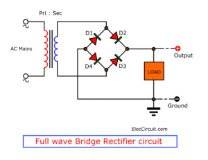
The full wave Bridge Rectifier
If we have a single secondary winding and 4 diodes. You should use the full-wave bridge rectifier.
It is better than a normal full-wave rectifier with 2 diodes.
Why?
Read below you will get an answer.
The working of the circuit
I will explain to you the working of the circuit in 2 steps.
Like the past circuits, the signal of the secondary winding is a sine wave. In 1 cycle has a positive and negative voltage.
That is… Supposed that…
The first step is a positive voltage. See in the circuit diagram. Both diodes D2 and D4 are forward biased.
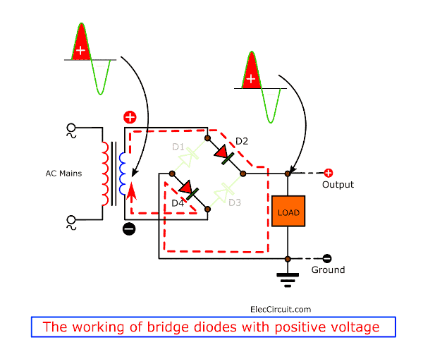
The working of the bridge diodes with the positive voltage
So, the positive electrical current can flow through to D2 and D4 to the load with full power.
While D1 and D3 are reverse biased. So they do not conduct the electrical current.
The second step is negative. It switches the polarity of the secondary winding. From positive into negative and the negative into positive.
So, both diodes D1 and D3 are forward biased. Then, the positive current can flow to D1 and D3 through the load with full power too.
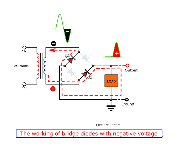
And, D2 and D4 are reverse biased. They do not work or not conduct the electrical current.
We will see that the load get only positive voltage. It is full wave rectifier. Because the diodes control the direction of the electrical current in one-way only.
If you do not understand enough.
See the graph below.
Why should Bridge rectifier
- Use a lower voltage of the secondary winding. To reduce the size of the transformer.
- Keep diodes cold down with pair of diode working.
- Cheaper
Three types of diodes rectifiers above make the pulsating DC.
But our electronic circuits need a smoothed electrical current only.
What are we looking for?
Filter
A filter is an answer. It smooths a pulsating DC from either a half-wave rectifier or a full-wave rectifier.
Often we use electrolytic capacitor is the filter.
When there is a high voltage. A load gets full of energy. While the capacitor will store that energy too.
After that, the voltage is lower down. But The load still gets energy from that capacitor give them.
Read more to learn more.
Filter in half-rectifier circuit
If we add an electrolytic capacitor to a half-wave rectifier circuit. See image.
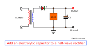
The waveform of the signal across the output changes. It is a more smooth DC voltage.
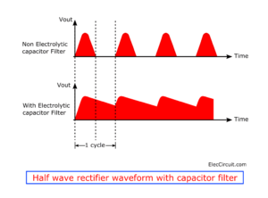
If we try to change the capacitor is many values. We will see that more capacitance, this energy from capacitor for long. It is a great filter. So, DC voltage is more smoothing.
What is ripple and how to reduce it
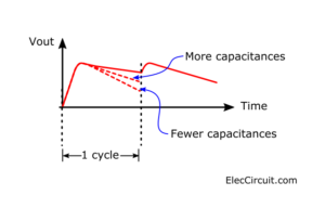
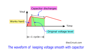
Step up—In the first period of time. the transformer and diodes work hard. They need to drive a heavy electrical current. Because they are supplying the load and charging the electrolytic capacitor.
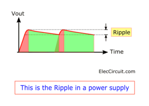
Step down—When the voltage rises to the peak. Then, in normal, the voltage begins to low down in a curve form. But the electrolytic capacitor gives the energy to the load instead. The voltage does not fall to zero. Before the next pulse arrives.
When we zoom in the waveform in the image.
The difference between the “Peaks” and ” Lows” called “Ripple“
Why is ripple important?
The ripple values are lower than 1V. We can hear an annoying hum in the background of power amplifiers. Or See a distorted picture gradually move down the screen on video.
Our aim is to reduce the ripple to zero.
But in this circuit, we need a more capacitance to smooth the ripple.
Also, we have many ways to reduce ripple. Even a regulator circuit which I will explain you later. Please wait to continue reading.
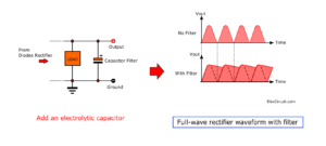
Smoothing the full-wave rectifier circuits
In the image, This is full-wave rectifier waveform. It is the same both a center-tapped transformer and a bridge rectifier.
Like the half-wave, we add the electrolytic capacitor across a load. But it is better smoothing.
See in the image right. With capacitor filter. It works a little only. Or you can use lower capacitance with the same ripple level.
So now people like to use a bridge rectifier power supply. Me too.
Read more: another site about unregulated power design
Designing unregulated power supply
Some people do not like math. Me too.
You read to here. Sure you want to build the AC adapter or unregulated power supply with yourself.
It is without complex calculations.
This is easy and cheap.
But you need to be careful. The AC mains can kill you. Do not touch the high voltage. You must insulate or enclose all exposed AC line connections!
You should unplug the power cord. If you assemble or service the circuit.
Choosing right components
In a simple full-wave circuit or unregulated power supplies above.
We have to choose the right components to load works best performance.
A transformer is the best
According to the principles explained earlier.
Suppose the load uses the DC energy of approx 9V at 100mA.
We need to design a power supply is.
- Give DC 9V stable voltage output.
- Supply the current a least of 100mA.
The transformer is the main power of the circuit. We should the right transformer. Enough and Fit and Save money.
- Use the current at least twice that load wants. Sometimes the load may eat too over. We should support it.In this is 100mA x 2 = 200mA (approx).Of course, You can use more the electrical current. For example, 1A. But it is bigger and expensive than this one.
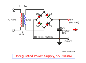
- Use the voltage to match the load wants. We should use the transformer having a secondary winding of 6.3V. Why? Because when AC convert to DC. The voltage will rise by about 1.414 times.We can calculate of 6.3V x 1.414 = 8.9V. or approx 9V DC.So that we do not should use 9V AC. Because of the DC voltage becomes about 12.7V(no load)
Rectifier Diodes
Like that transformer, we should use the diodes that enough, too.
We should use the current and peak inverse voltage (PIV) more than twice that we use.
In this, we should use the current is 200mA. But we need to use 1N4007.
Because It can withstand a 1A current and a 1000V.
And, They are the same prices as 1N4001(1A 50V)
Others Diodes Tips
- Unity is power—imagine you cannot work hard with a big project. But your friends can help you. It is like a diode. Suppose you use the current of 1.5A.In normal you should use 1N5402(3A 200V). But you no have it. How?
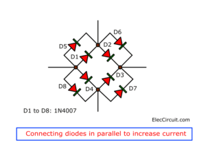
You may use the Unity of diodes. If we connect diodes in parallel. They can pass the current more.
In this, you add a 1N4007 as the image below. They can get the current about 2A. - Use the bridge diodes—Four in one. Inside has four diodes connect each other in the bridge form. It’s convenient. But the price is higher.
In the example circuit above, the output about 8 volts (No load 8.4V) power supply at 100mA. When we apply the power cord to AC line, the 120VAC/220VAC/230VAC fed to a step-down transformer-T1 via the on-off switch-S1 and the 500mA fuse-F1. It will blow if the current through the output terminals is too high.
The 6V AC output (approximately) from the transformer is rectified by a bridge rectifier, which We want to save money with not use the normal Bridge Rectifier, we can easily use the 4 general purpose 1N4007 rectifier diode D1 through D4. Now they rectified AC (Alternating Current) to DC (Direct Current).
This pulsating DC output is filtered via the 1000uF capacitor-C1, it acts as a storage capacitor. Now the pulsating DC smooth look like DC voltage from the battery.
Electrolytic capacitor size
Then, choose capacitance of the electrolytic capacitor enough. Which it determines by the current of power supply.
In the normal rule, we use 2,000μF per ampere.
But should more than 1,000μF even the current lower than 1A. So, in this circuit, we use 1000μF.
The capacitors must have a DC working voltage (WVDC) of at least 12V.
Add one or more capacitors in parallel with C1 for more capacitance
Reduce the ripple
Do you know that ripple makes the output is low voltage?
Yes, see the graph in the image above.
And, you know the ripple happens with loads. And, the large capacitors is our hero.
Also, The ripple value not should over than 1V. As above.
If your friends don’t have an oscilloscope. How can friends know the ripple value?
Here is an approximate formula for determining the amount of ripple on an unregulated supply is:
Vrip = ILoad * 0.007 / C
Vrip = ripple value
ILoad = the current of the load
C = Capacitance of Capacitor
In this circuit above.
ILoad is 100mA or 0.1A
C is 1000uF or
We can calculate value of ripple is (0.1 * 0.007) / 1000e-6 = 0.7V or 700mV.
The value of peak to peak ripple measured from the graph is 628mV.
Then try to change capacitor is 2000uF. The ripple is lower down to 0.35V
This is a simple equation to choose the right capacitor to reduce the ripple of the power supply.
So, we add more capacitance. But It is too big and more expensive.

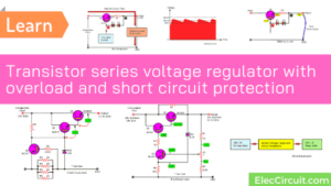
It is a better way. If you use the regulated power supply. Which we will learn next.
.
Related Posts

I love electronics. I have been learning about them through creating simple electronic circuits or small projects. And now I am also having my children do the same. Nevertheless, I hope you found the experiences we shared on this site useful and fulfilling.