Let’s use the ULN2003 stepper motor driver for any microcontroller, Arduino, PIC, MCS51, and others. But we can’t drive the motor directly. We need to have a good helper. I recommend ULN2003.
Why should we use it?
It is an IC driver relay, a motor widely used for driving many relays. It is suitable for use in automated control tasks that have a total of 7 operation channels, working independently with each other. Or we called 7 Channel Transistor Arrays.
We can use it to work instead of many transistors. Therefore making the circuit smaller And less complicated as well.
ULN2003 Features(Why use it)
- We can use logic devices like Digital Gates, Arduino, PIC, etc to control it directly.
- It includes 7 high-voltage and high current Darlington pairs inside
- Each pair is rated for 50V and 500mA
- We can trigger the Input pins by +5V
- All 7 Output pins can connect to drive loads up to (7×500mA) about 3.5A.
- Available in 16-pin DIP
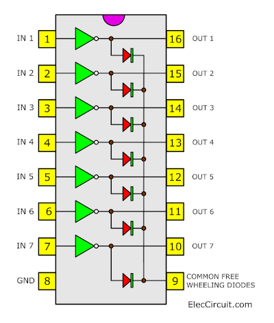
ULN2003 Datasheet and pinout
See in the block diagram or its pinout.
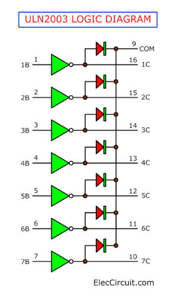
See the logic diagram in IC. Inside, there is already a diode. Therefore, when connecting to the Relay, no additional Diode must be connected.
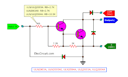
ULN2003 internal circuit and Pin Configuration
The internal circuit uses connecting Darlington transistor. Resulting in using only a small amount of current to drive the relay.
How to use each pin
- The INPUTs
Pin 1 to Pin 7 is input 1 to input 7. They have the 7 Input pins of the Darlington pair, each pin is connected to the base of the transistor and can be triggered by using +5V. - The OUTPUTs
Pin 10 to pin 16 is Output 1 to Output 7. They are respective outputs of seven input pins. Each output pin will connect to the ground only when its respective input pin is high(+5V) - The Ground of the circuit
- COM Use as test pins. They are optional to use
Recommended: How does an SCR work
Example ULN2003 circuits
What is more? see how it in example circuits below
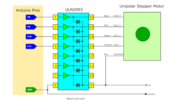
Arduino ULN2003 stepper motor driver circuit
See the simple circuit below. Using ULN2003 stepper motor driver circuit for Arduino.
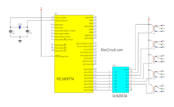
PIC Microcontroller 5 Relay Driver circuit
Then, see the 12V Relay driver circuit using the PIC microcontroller (PIC16F877A).
Stepper motor driver using a parallel port
This is an easy-to-build stepper motor driver that will allow you to precisely control a unipolar stepper motor through your computer’s parallel port. With a stepper motor, you can build a lot of interesting gadgets such as robots, elevators, a PCB drilling mill, a camera panning system, an automatic fish feeder, etc. If you have never worked with stepper motors before you will surely have a lot of fun with this project.
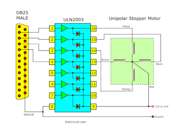
But These Stepper Motor Controller Connection Diagrams use 2 port voltage are 5Volt and 12V and four resistors, a Zener diode.
The Four-Wire Connection the ULN2003 (High-Voltage High-Current Darlington Transistor Array
)/ MC1413 is a 7-bit 50V 500mA TTL-input NPN Darlington driver. This is more than adequate to control a four-phase unipolar stepper motor such as the KP4M4-001.
Click to Download the PDF file of this post

Related Posts

I love electronics. I have been learning about them through creating simple electronic circuits or small projects. And now I am also having my children do the same. Nevertheless, I hope you found the experiences we shared on this site useful and fulfilling.
je domende les livers
Hello any one can help me I need the program of 16f877 for relay module controller as ON/OFF
Pls can I get the PDF file .thanks
Hello
I send you PDF file to your email.
Thanks
Thanks very much sir God bless you
You’re welcome God bless you too. 🙂