This is a bass booster circuit that uses transistors as a base. It is designed to increase the low frequency of audio.
They are cheaper than ICs or normally circuit. Because of use each channel only 2 transistors together with resistor and capacitors approximately ten parts only.
In the circuit, Adjust potentiometer trimmer, 10-50K to turns a level of bass level up and down as you want.
Look:
Figure 1 is the circuit diagram on mono or signal channel. But the PCB layout below is stereo or dual-channel. Most people like it.
Recommended: Learn transistor circuit works here
Working principle
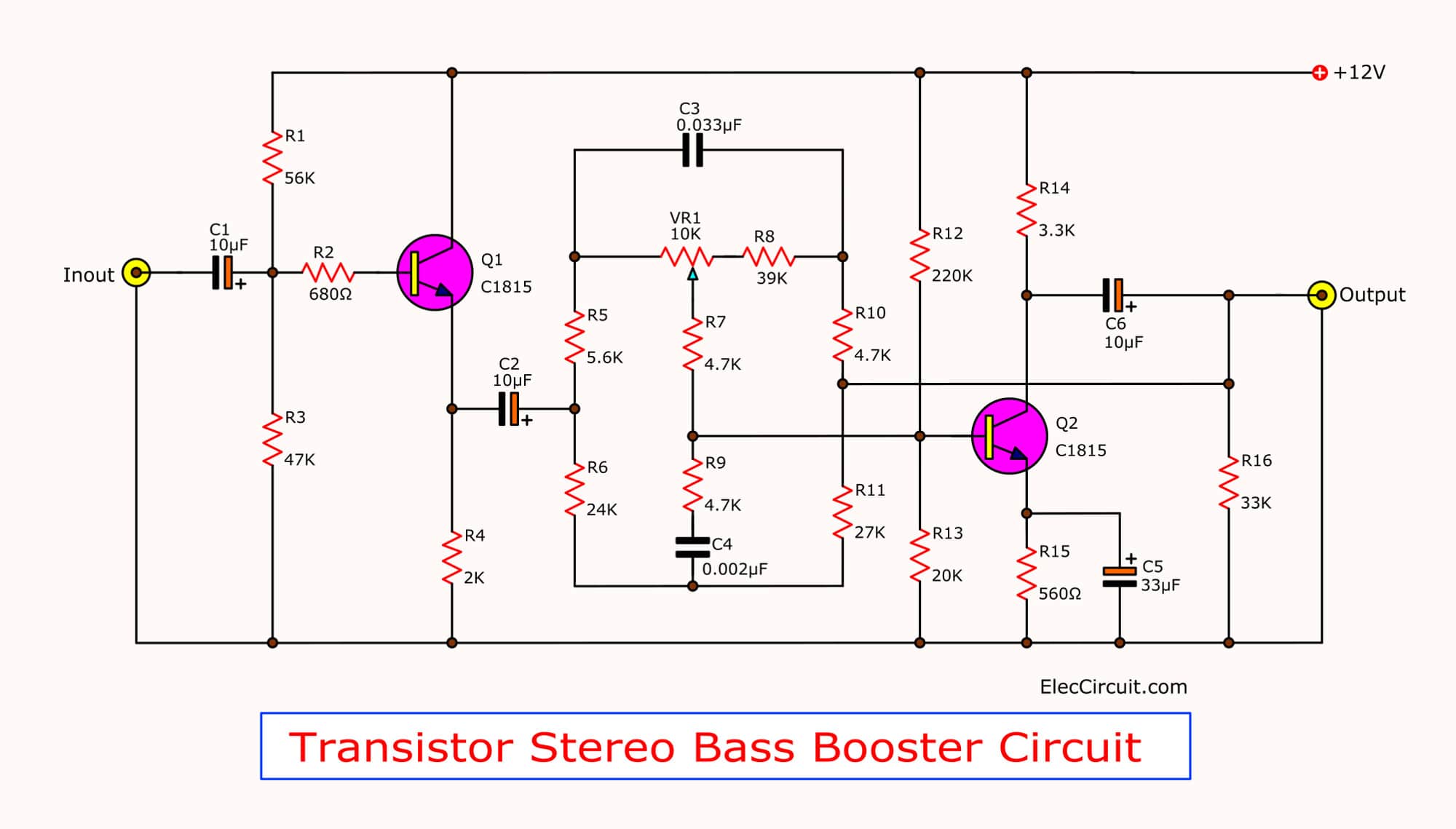
The Transistor stereo bass booster circuit
I do not like to read a lot of text. You may also same me. So, I keep the shortest explaining you.
Here is the step process:
C1 coupling an input signal into the base circuit of Q1 at pin B.
Both resistor R1 and R2 are biased currents to Q1, for first preamplifier section.
Then, a higher signal comes out of E of Q1. The voltage does not change but higher current. It keeps impedance to low.
To drive RC networks to separate and increase the bass signal to higher from other frequencies.
But the signals come out of the R C networks will be too lower.
So, we need to amplify to more with Q2 and a few parts.
After that, some signals at output goes back as a feedback signal to the R-C network circuit. To boost up a signal again.
How to builds
Building this project is easy. Just use a 12V power supply regulator that is smooth enough.
It may be connected via R-100 ohms and has C-100uF 16V to the ground.
As Figure 2 All resistors in the circuit use 0.25 W.
Then, the wiring to a circuit and various components. You can view the example in Figure 2.
But look carefully for the polarity of electrolytic capacitors, and legs of the transistors. Must be correct only!
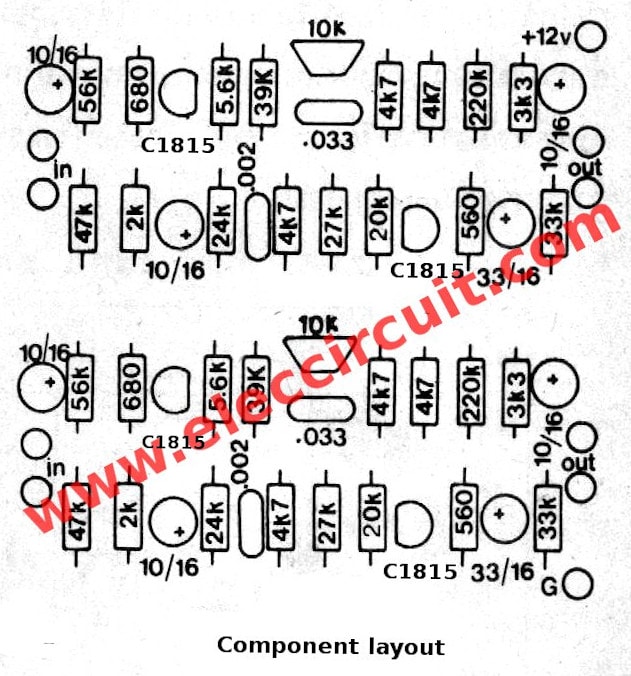
Components layout of Transistor stereo bass booster
Note:
This circuit requires 12V DC voltage Regulator.
The components List
Q1-Q4: 2SC1815 or 2SC945 or 2SC458, NPN transistors
Electrolytic Capacitors
C1,C6: 10uF 16V
C5: 33uF 16V
Polyester Capacitors
C2: 0.033uF 50V
C3: 0.0022uF 50V
0.25W Resistors, 5% Tolerance
R1:56K
R2: 680 ohms
R3: 47K
R4: 2K
R5: 5.6K
R6: 24K
R7, R9, R10: 4.7K
R8: 39K
R11: 27K
R12: 220K
R13: 20K
R14: 3.3K
R15: 560 ohms
R16: 33K
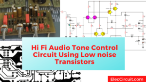
Also bass booster circuits below

Related Posts

I love electronics. I have been learning about them through creating simple electronic circuits or small projects. And now I am also having my children do the same. Nevertheless, I hope you found the experiences we shared on this site useful and fulfilling.
wew… It work… Nice bass..tnx..plzz tell me what transistor pre amp with mid range that work??coz i build the tri amp and the three band using ne5532..its not woking..plz
Hi Mr newbie,
Thanks for your feedback.
i want to run this same circuit using 5v,because iwant connet to pc supply (USB port)
so what the changes i must do ??..sir
evening sir , is the wattage of its resistor is 1/4 W ?
Good is sid
Hai eleccircuit is dest
Does this amplifier outputs only amplified low frequencies, or it outputs high and low frequencies, but with the function of manipulating the low frequency amplification?
Hi Jesus,
Thanks for your question.
This circuit is modified from a general pre tone control circuit. It is an easy circuit. It gives a lower frequency signal. Which may be enough for general listening.
But if you want a low-frequency sound that can be specified for certain frequencies such as 60 HZ
See: https://www.eleccircuit.com/cheap-car-subwoofer-filter-circuits/
I want to help you if it’s helpful.
Copy permission, thank you
Hi ripto,
Yes you can copy. And please make a credit like to my site for this circuit diagram.
Thank you.
Dear sir where to connect ground supply or take out ground
Hello Sanjeev Kumar,
Yes, the ground is the ground of the power supply too.
Thanks
من از شما بخاطر زحمتهای زیاد سایت زیبا وکارهای فوق العاده خوب و اموزنده تشکر و قدردانی میکنم
ارزوی بهترینها را براشما دارم
Hi,
You’re welcome. My dad and i became more energized when we saw your message. I feel happy. I will continue to make websites about electronics. 🙂
very very good
Hi,
Thanks for your feedback. 🙂