My friends ask for simple Traffic light controller circuit. So, today let’s look at three models of Traffic light control system without a microcontroller. They use just only simple digital circuits. So easy! You can build them on a breadboard. It is basic to learn basic digital for up to level up.
There are three circuits below.
First: Traffic light circuit
They use the LEDs for display and the digital circuit as based.
This circuit includes IC-4027, CD4017, IC-555 and a few parts so easy and cheap.
This circuit is designed first. We use many circuit to mix together.
As circuit in Figure 1
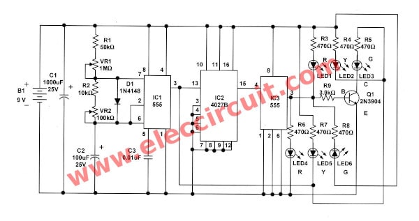
Figure 1: The schematic diagram of first circuit.
Learn: How to use 555 timer circuits
How it works
-The IC1-NE555 will generate the square wave pulse out to pin 3, to determine the working state of IC2.
The frequency of IC1 will depends on R1,R2,VR1,VR2 and C1.
The VR1 is used to adjust the time of a green LED show.
And, the VR2 is used to adjust the time of a red LED show.
Then this signal is sent to IC2, that is connected as T-flip-flop.
The T- flip flop will change the state every toggles on leading edge of clock signal from IC1.
The IC2 will supply the output at pin 15. But it cannot directly drive the current to LEDs.
Thus, we need to use IC3 as buffer circuit, to drive LEDs. This circuit can good work.
But there are disadvantage, the yellow light will light all the time.
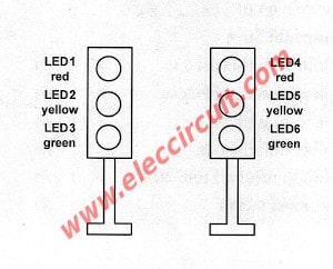
Figure 2: placing of LEDs in first model.
Learn more: Great electronic supplies stores lists for you
Parts you will need
0.25W Resistors tolerance: 5%
R1: 50K
R2: 10K
R3-R8: 470 ohms
R9: 3.9K
VR1: 1M Miniature skeleton preset
VR2: 100K Preset
Capacitors
C1: 1000uF 16V, Electrolytic
C2: 100uF 16V, Electrolytic
C3: 0.01uF 50V, Ceramic
Semiconductor and others
LED1, LED4: 5mm Red LED
LED2, LED2: 5mm Yellow LED
LED3, LED6: 5mm Green LED
Q1: 2N3904, NPN 40 Volt 0.2 Amp transistor
IC1,IC3: NE555____Standard Timer Single 8-Pin
IC2: CD4027, DUAL J-K MASTER/SLAVE FLIP-FLOP
Both circuits require enough power supply. Do you have this one? If you do not have it. Look:A lot of Power supply circuit
The second: Traffic light circuit
As above, we can improve the various disadvantages and use a fewer ICs.
Which are easier to understand because as small size circuit.
This circuit include 3 main section:
1. the oscillator use IC1
2. the times generator use IC2
3. The display using LED by the transistors to drive LEDs
How it works
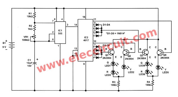
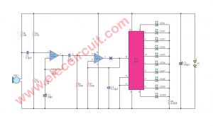
Figure 3: the schematic diagram of the traffic light circuit in update version.
In the oscillator, IC1 is connected as the astable multivibrator circuit to generate the frequencies.
This frequency is determined by R1,R2,VR1,C1.
Then, this output frequency will appear at pin 3 of IC1 into pin 14 of IC2.
Which IC2 will be connected as the decade counter circuit.
Next, the IC2’s pin 14 will continuously count the input signal, and display the output “1” on pin 3, 2, 4, 7, 10, 1, 5, 6, 9 and pin 11 respectively.
While pin 14 is “1” the pin 3 is “1”, but others pin will is “0”.
Then pin 14 get “1” again the pin 2 is “1” instead, the pin 3 and others will is “0”.
The output is “1” flash to output pins 3 to 11 as above.
Then, it will cycle back to the pin 3 again.
Read also: DIY Flashing Bicycle LED Taillight Circuit
All LEDs is installed as Figure 4.
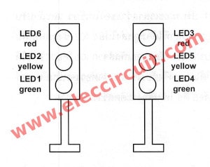
Figure 4. placing of LEDs in improved model.
-The output voltage at pin 3,2,4,7 will make Q1 works.
-Then the green-LED1 and red LED3 glow.
-Next, the output voltage at pin 10 will make Q2 works.
-Thus the current will flow to both the yellow-LED2 and red-LED3 light up.
-Next step, the output voltage at pin 1,5,6,9 makes Q3 works, so there are the current flow to the green-LED4 and red-LED6 glow up.
-Then, there is the output voltage at pin 11, so makes Q4 works.
-Next there a current flow to the yellow-LED2 and the red-LED3 glow up.
-And the output will cycle back at pin 3 again.
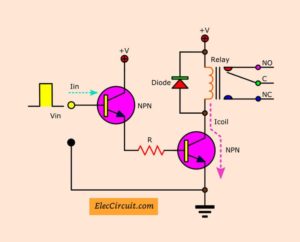
If change from LEDs is relays will make we can control the high power lamp.
Parts you will need
Resistors
R1: 10K_1/4W Resistors tolerance: 5%
R2: 1K_1/4W Resistors tolerance: 5%
R3, R4: 180 ohms 1/4W Resistors tolerance: 5%
VR1: 100K, Miniature skeleton preset
Capacitors
C1: 1000uF 16V, Electrolytic capacitors
Semiconductor and others
D1-D8: 1N914 or 1N4148, 75V 150mA Diodes
LED1, LED4: 5mm Red LED
LED2, LED2: 5mm Yellow LED
LED3, LED6: 5mm Green LED
Q1-Q4: 2N3904, NPN 40 Volt 0.2 Amp transistor
IC1, IC3: NE555, Standard Timer Single 8-Pin
IC2: CD4017, Decade counter with 10 decoded outputs IC
B1: 9-volts battery
Related Posts

I love electronics. I have been learning about them through creating simple electronic circuits or small projects. And now I am also having my children do the same. Nevertheless, I hope you found the experiences we shared on this site useful and fulfilling.
I would like to get some instructions on how to repair a simple house electric fan. I am an amateur electronic enthusiast. Thank you.
Thanks to all of you for the great circuit designs.
Rob54
Hi, Robert Swatosh
Thanks for your feedback.
This circuit does work. However, the designing has to be done properly. Please short the two yellow LED’s so that they glow simultaneously in both the cases of before turning green and before turning red.