Have ever you see SCR? Some may use it instead of switches and relays. Because we have seen it works high speed and quiet.
Sound good, doesn’t it?
If we are going to learn how does SCR Works. Let me explain them to you.
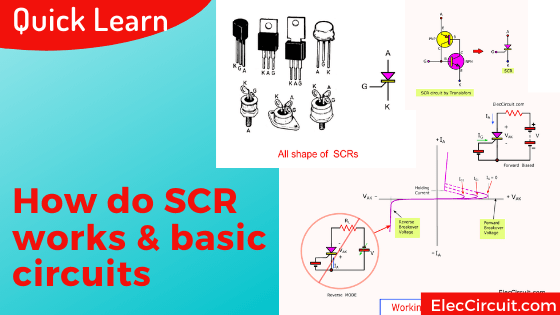
What is SCR?
SCR is a semiconductor and thyristor device that is important for a power electronic circuit. SCR stands for Silicon Controlled Rectifier.
Sure, these words are not necessary for you. You don’t have to do exams. We just use it well enough, right?
SCR Application
How can we use SCR? a lot of applications for example:
- Use to load current, 0.8A to 10000A or more.
- Lighting control
- Speed control of motor
- Rectifier circuits to convert alternating current to direct current.
- Or Convert from direct current to alternating current.
- Use instead of a switch or a relay to turn the load on and off.
- Switch circuits that require very high speeds.
- Need a spark-free switch that works.
- Used instead of a very high current diode. The advantage is that it is controlled by small currents. Like transistor.
- And more.
Which is your want?
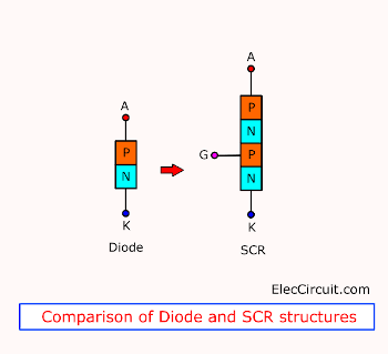
Structure and equivalent circuit
Imagine you take a hammer to smash an SCR. You see, it is a four-layer structure. And has 3 PN junctions. Some called 4-layer PNPN Diode. Because it passes current in only one direction.
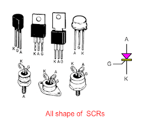
SCR symbol
Compare Diode and SCR symbol. The SCR is similar to a diode. Just have more a G leg only.
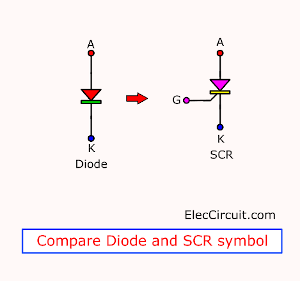
Also, it has 3 leads similar to a bipolar transistor. But names are a difference, include:
- “A” stands for Anode
- “K” stands for Cathode
- “G” stands for Gate
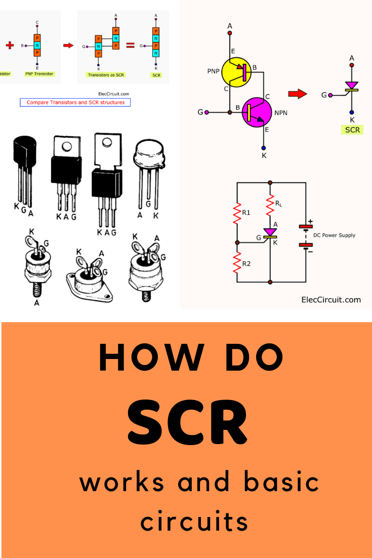
See Structures of SCR again. Now, we compare it with transistors.
We are more familiar with Transistors than SCR.
So…
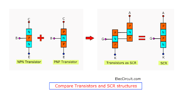
We can modify both types of transistor NPN and PNP to the SCR easily.
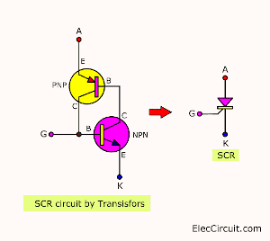
Here is connecting two transistors as an SCR transistor circuit.
If compare circuits both.
- The Gate of SCR is a collector(C) of the PNP transistor and Base(B) of the NPN transistor.
- Anode of SCR is Emitter(E) of PNP transistor.
- The cathode of SCR is the Emitter(E) of the NPN transistor
We will learn it works from the example circuit diagram later(below).
What is more?
Working of SCR
It is difficult to explain how SCR works are easy to understand. But I will try to reduce Its in-depth details. Leaving only important principles for basic use only.
In a normal SCR circuit. We always connect a load in series with “A” lead and positive supply. But a cathode(K) connects to the negative supply.
Here is the working of SCR under two heads:
Open gate mode
See in the circuit.
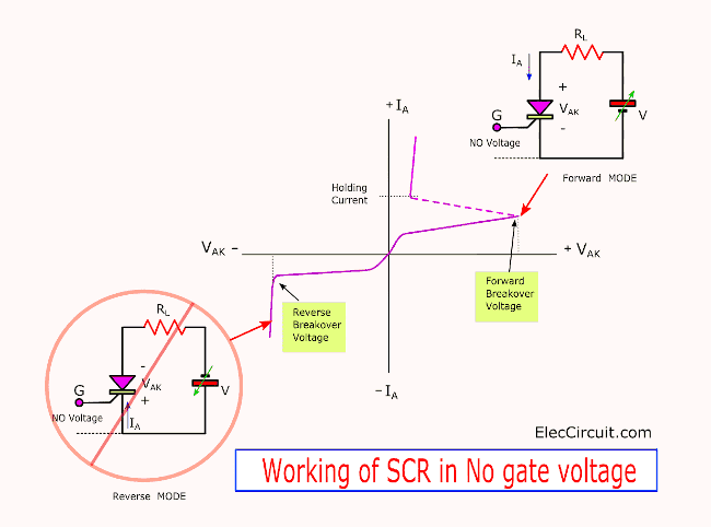
When no voltage to the gate.
There are 2 cases to learn:
- Forward BiasedUnder PN junction of SCR is a situation as in an NPN transistor with a base open. Therefore, no current flows through the load RL and the SCR. But, if we continually increase the voltage supply. Until a reverse-biased point breaks down.
Make the SCR now conducts heavily. It is a “Turn-ON” state. But in normal we do not add a high voltage supply like this. We called Forward Breakover voltage, forward-biased. - Reverse Biased In contrast, we turn the polarity supply voltage. It is like a reverse bias of a diode. If we increase more voltage up and up. Until to one point will make SCR conduct heavily current, and damaged in end. We called the Reverse Breakover voltage.
Therefore, we must use a lower voltage than the Breakover voltage. The characteristics of each SCR are different. We should study the information in detail.
Not only that.
You would not use SCR with no gate current, Right?
Enter gate voltage
While we trig the gate with entering a little current. It is positive if compare with the Cathode. Makes SCR works the correct way. We often use this.
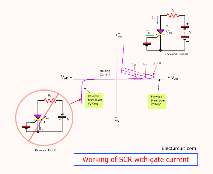
But do not forget the voltage across A and K must be lower than the break overvoltage.
When SCR conducts current through Anode to Cathode. Then, it keeps working on this current. Even if we remove the gate current already.
If we reduce the current flows through Anode to Cathode leads to a holding current. It causes SCR to stop.
See in the graph:
The holding current is the lowest current that makes SCR still works.
Both IG1 and IG2 indicate the gate current. If we enter this more current it will work fast.
Size and shape of SCR
Currently, there are many types of SCR depending on the application. And there are many SCR specifications or qualifications as well.
We can divide it into 2 properties. These are:
- Can withstand a current of 0.8-2000 amperes.
- Withstand pressure drop across it. Maybe about 200V to more than 1000V etc.
With these qualities, there are different shapes of SCRs. See the SCR wiring diagram below.
Sample SCR popular for me
Sometimes you may wonder. Can your existing SCR be used interchangeably? Or choose which one to buy Most economical.
Let me give you an example of 6 SCRs that should be used.
- 2N5060: 30V 0.8A, TO-92. Looks like 2N2222 transistor.
- T106D1: 400V 4A SENSITIVE GATE SCR, TO-220
- C106B1: 200V 4A A, TO-202
- 2N6507 SCR: 400V 25A, TO-220
- C38M: SCR 600V 35A, TO-65
- 2N6509: 800V 250A, TO-220AB
What is more?
How to pick SCR
When using the SCR, consider Its limits. Which the manufacturer will always specify.
Important things to know:
- 1. VBO (Forward breakover voltage) is the voltage causes SCR to start conducting without no gate current. Or, The maximum voltage that SCR can tolerate.
- 2. IFmax (Maximum forward current)is maximum currents can flow in SCR without damage to the SCR.
- 3. IGTmin (Minimum gate triggering current) is the minimum gate current that can trigger the SCR.
- 4. IH(Holding current) is the lowest current that flows through A-K. That can keep on SCR works.
- 5. VB (Peak reverse voltage) is the return voltage that will fit the SCR Can break down
For example, T106D SCR is 400V 10A.
Means an SCR of VBO = 400 V and
IF (max) = 4A. But Average current: 2.5A, IH = 20mA , IGT = 200uA.
So we should use SCR, not over its capability. It may cause too much heat and damage in the end.
How SCR is triggered
We can trigger in many ways. I would like to divide by 2 types of power supply:
1. Using DC Power Supply
We often use it with a DC power supply. It is so easy.
See:
It shows the principles that make SCR conduct current by direct current.
The figure has 2 circuits.
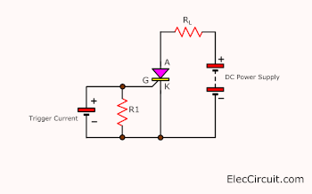
The trigger current is separate from the power supply.
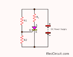
2. Get trigger current from a single power supply with divider resistors.
But both circuit has the same principle.
We apply a positive supply to an anode of SCR. And negative to the cathode.
Then, enter a little current to the gate of SCR. We called a trigger current. And, this voltage must be a positive only, when compared with a cathode.
If the level of the gate current still lower than the trigger current. SCR will not work. But when SCR conducts current now. It will keep on working at all. Even we will reduce or remove the trigger current.
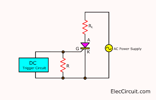
2. Using AC Power supply
Most we use SCR as the power electronics switches. To turn on-off any load circuits. But SCR conducts current in one way only. Or DC voltage as above.
However, we can use SCR in AC power supply.
Imagine you can control a motor, a lamp, and more on AC main using SCR.
Sound good, doesn’t it?
I will divide into 2 cases.
1. Triggering with DC current.
Look image the circuit. The trigger circuit is DC voltage. It can control SCR on-off.
Are you understand? Look:
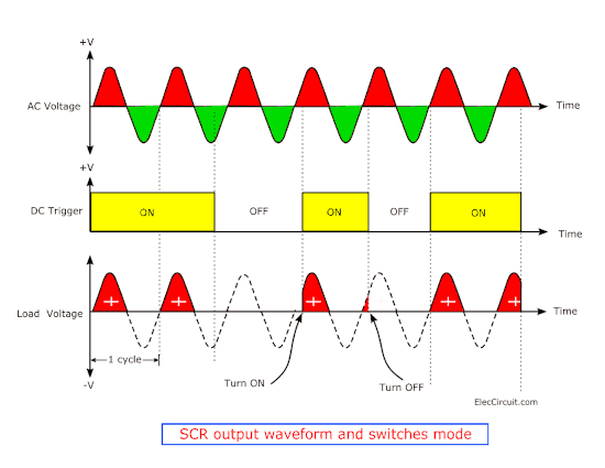
Look at the signal image at various points of the SCR circuit. The signal passing through the load will become a Pulsating DC voltage.
It is a half rectifier circuit and a switches circuit. We can control by the trigger circuit.
Suppose that we enter the DC trigger voltage (Turn ON). It is in phase with the AC supply. Makes SCR conduct current to load in a waveform.
I feel uncomfortable, Cannot describe words well. You look graph better.
Download This
All full-size images of THIS POST as PDF in the Ebook. Thanks, support me. 🙂
Sample simple circuits using SCR
If you still do not understand. You may look at the circuit below. To increase your imagination
The transistor lat as SCR trigger
This circuit works similarly to an SCR. When the trigger input is high, Both transistors Q2(PNP transistors) and Q1(PNP transistors) will work. Therefore, the current flows to the base pin of Q2, which has a voltage of 0.7 volts at resistor R1.
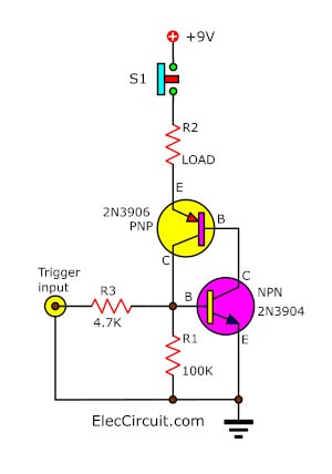
When we cut the trigger voltage, the transistors can continue to work, because of the base current. We can reset the circuit by cutting the power supply circuit. Which this circuit we press the switch S1-reset button only.
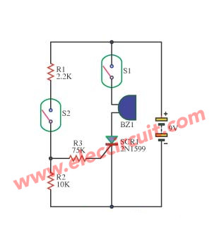
Audio magic-using SCR 2N1599
This circuit can be used to perform magic using only a permanent magnet to control the magnetic reeds switch only. It can be controlled using a buzzer to make a loud noise.
Working principle of the circuit
Normally the BZ1 is not loud.If you want BZ1 rang out, you just tap the reed switches S1 and S2 to close the circuit with the permanent magnet.
The R1 and R2 act as divided voltage from the 9V-battery. For the R3 is current limiting resistor, to trigger the pin to the gate of SCR1. Then, it conducts current to flows through the BZ1 emit a loud out.
And, if you want to come back in normal conditions. Move the permanent magnet from the reed switches S1 and S2. Which make SCR1 stop conduct current. Therefore, no current flows through BZ1, and no sound.
Not only that, You can read more others circuits using the SCRs:
- Sound Activated Switch Circuit with PCB
- Converts power supply to automatic battery charger using SCR-CA723
- Automatic battery charger circuit
- 4 Home disco light circuits using SCR-555-4017
- Five Battery low voltage alarm indicator circuits
- Surge protection circuit for power supplies
- 4 ideas of One LED flasher circuits using transistor, IC, UJT
- Xenon Strobe Light using SCR
- Sensitivity contest circuit
- Simple electronic fuse circuit
- Automatic night light circuit using SCR
- SCR Mini Power Inverter
Related Posts


I love electronics. I have been learning about them through creating simple electronic circuits or small projects. And now I am also having my children do the same. Nevertheless, I hope you found the experiences we shared on this site useful and fulfilling.
Thanks.
So educative and nice
Hello Jamir,
Thanks for your feedback.
This Circuit is a Great way To Teach SCR Basics!!1 This was how i was taught in College. WELL DONE!!!!
Hi Mr ohm 1970 my friend,
Thanks for your feedback.
Wishing you happiness and prosperity in this New Year. Enjoy each day.
Nice and simple explanation.
Why don’t you explain other components too
Good, simple circuits and easy to understand
Thanks a lot. Your sound is a power for me.
Learning is continuous.Goodwork here.
Tried to use visa gift card to order book.It did not work.I am not the only one that tried!I order electronic parts as well as ham gear with a gift card .
Hello Jake,
Please try again with other browsers. My Friend uses a Mastercard gift card, no problem.
Thanks for your support
Apichet
Love your site. Makes learning easy. Extremely grateful for the help you are providing.
Hello John Higgins,
Thanks for your support.
Have a great day.
Hello,
Wonderful explanations that belong only to an efficient, dedicated teacher WITH PASSION FOR WHAT HE INTENDS TO DO.
LET ME INFORM BY Email ABOUT ALL THE BOOKS AVAILABLE FROM YOU, from the beginner to the advanced hobbiest-AMETEUR.
NEVER GIVE UP… THERE ARE SO MANY TO FOLLOW YOUR FOOT STEP…
BEST WISHES TO YOU ALL…
WITH LOVE, HUGS AND KISSES YO YOU ALL…
Hello Appa,
I am very grateful for your compliment and your support of my eBook.
I will definitely continue to do what I have done.
Thanks so much.
Apichet
Thanks a lot. Awesome information.