An application a Signal amplifier circuit diagram with a set input-output ratio, specifically the AC signal amplifier in common electronic circuits. Most of these amplifiers will be fed back some signal to the input again. To reduce amplify rate down affects to reduce a distortion rate and reduce also the noise signal. The feedback signal may through a resistor, transistor, or diode Depends on circuit design.
But circuit is presented to use series of resistor adjustments and only 4 diodes and can set a signal amplifier ratio between input and output.
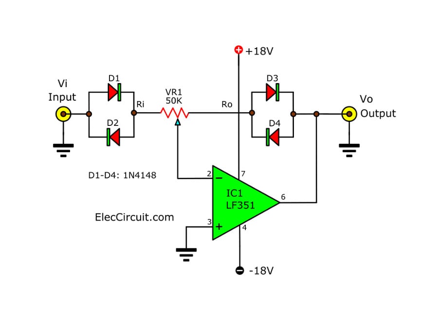
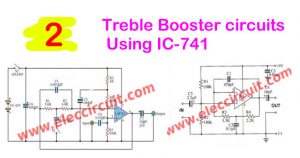
Figure 1 The signal amplifiers circuit can set input and output ratio
The circuit in Figure 1 amplifier sets the ratio between input and output. As signal amplifier for simple alternating current. By use the op-amp (IC1) is signal amplifier. And by some signal will be feed back through the diode and has potentiometer-VR1 about of 50 Kohms. To selects the output signal to come out three different models.
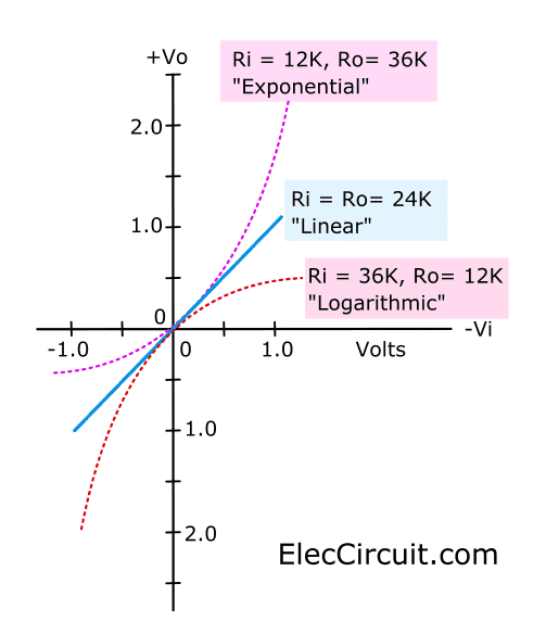
If adjust VR1 clockwise until the input impedance or Ri has value about 12Kohms cause the output impedance or Ro has value about 36Kohms will cause ratio between signal input and output is Exponential form or if Ri has value equal Ro or around 24 Kohms ,the output appears as a linear form. And if Ri has value 36 Kohms, The Ro has value of 12 Kohms, the output is logarithm form. As graph in Figure 1
The diode is a silicon type work in a high sensitivity switching form. The power supply so depends on the amplifier circuit that use op-amp types. In circuit use the OP-AMP number-LF351 has JFET is input of amplifier section which is low noise signal. We can use power supply from +9V to +18V. We can replace The potentiometer with fixed resistors in series
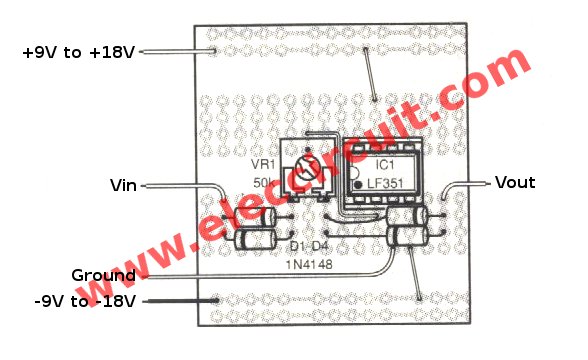
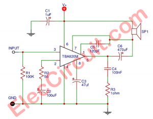
Figure 2 the components layout of this projects.
How to builds
This project is not used many components so can assemble on the universal PCB board as Figure 2. In the assembly circuit, Starting equipment lowest first to Beautiful and easy to the assembly. Start from Diode and then resistors and sort of high continuously.
For the device has various polarity should be careful in the assembly circuit.
The components list
Potentiometer
VR1: 50K, standard horseshoe-shaped resistor
Semiconductor components
D1-D4: 1N4148, 75V 150mA Diodes
IC1: LF351, Wide Bandwidth JFET Input Operational Amplifier
Others
The universal PCB board.
Related Posts

I love electronic circuit. I will collect a lot circuit electronic for teach my son and are useful for everyone.
An impressive range of useful free circuits and data for all abilities – keep up the good work – I am 71, but retired from the electronics world at 60 but still keep up with my hobby since I was 11 – and I am still learning new things.
Hello Alex Glass,
Thanks for your visit. How are you? I am very impressed.
You are an example of learning new things. Age is really just a number.
I promise to keep electronic, simple content.
Have a great day.
Thanks again,
Apichet
Frequency work?