Today I would like to share with you the working principle of a DC-to-DC Buck converter, or as some people may know it, a step-down DC-to-DC converter circuit. Since it is highly effective and cheap, it is very popular nowadays. So, I want to teach my daughter its working principles in a simple way, and we hope this experience may be helpful to you as well.
It will reduce a high input voltage into a low output voltage that is suitable for a load or various uses.
It can also be referred to as a “buck converter,” often casually.
If you would like to support us, you can buy me a coffee.

Note:
I will be explaining it with simple concepts based on my experience teaching my daughter. Which, in some parts, may not be in accordance with academic principles. But let’s just understand the general principles first. Then we’ll go into more detail later.
According to the ancient saying, “It doesn’t matter whether it’s a black cat or a white cat; just catching a mouse is enough.”
Learn more: How it works and types
Why use the Buck converter?
The buck converter is an essential part of the switching mode power supply. Giving it much higher power efficiency than a linear power supply.
For example, we want to use a 3.7V 3W LED with an AC adapter of 12V 0.5A. But the voltage level is too high. So we have to lower the voltage of the AC adapter to 3.7 volts first.
What could we do?
What could we do? First, we need to find the current of the LED.
I = P / V
I = 3W / 3.7V
So, I = 0.81A
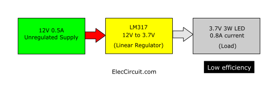
In this case, we might be able to use a linear regulator circuit, such as the LM317, as it can reduce the voltage to 3.7V while supplying a maximum current of 1.5A.
However, the AC adapter can supply only 0.5A of input current to the LM317. But LED requires a current of about 0.8A.
In principle, the linear regulator, or LM317, cannot increase the output current. It works similarly to a resistor, making the output current of the LM317 always below the input current, 0.5A. This will underpower the LED, making it less bright.
At this point, if you still do not understand, I will explain it to you more clearly.
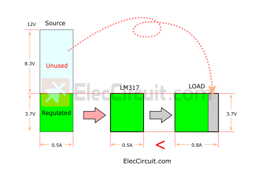
The block diagram illustrates why the linear regulators have poor performance.
Let the green square blocks’ height be the voltage level and its width be the current.
The LM317 block limits the voltage to 3.7V, whereas the rest of the excess voltage, around 8.3V, from the AC adapter voltage is left unused. So would it be great if we could convert this voltage into more current for the load?
Compare Electrical Energy with Water
The answer: Yes! But in linear regulator circuits, this is almost impossible. So instead, we should use the switching regulator, or “buck converter.”
Because it can reduce and maintain a constant voltage of 3.7V. And it can also increase the output current. Which is similar to converting the excess voltage into current.
It is like any other normal power supply that can output power (P), which consists of voltage (V) and current (I), by a simple equation: P = V x I.
We may compare the AC adapter and the LED (Load) to two water tanks of different sizes. The first tank measures 12 (V) x 0.5 (A), and the second tank has dimensions of 3.7 (V) x 0.8 (A).
If we filled the first tank with water and let the water flow into the second tank, would it fill the tank completely?
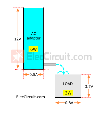
Of course it would, because the volume of the first tank is 6 (W) from 12 (V) x 0.5 (A) and the second tank is 3 (W) from 3.7 (V) x 0.8 (A). Normally, the water within the larger container can fill a smaller container fully.
The simple idea of switching regulators
Next, let’s understand the concept of a buck converter or a switching regulator. It uses the principle of high-frequency switching.
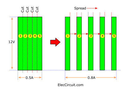
From the illustration above, we will let the electrical power of the AC adapter be represented by a rectangular clay with a height of 12V and a width of 0.5A. And divide it into five equal parts.
Then, we rearranged and spread them evenly so that the total width added up to 0.8A.
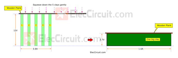
Next, we used a wooden plank to place it on top of the clay and press it down to 3.7V. As shown in the illustration above.
It causes all 5 pieces of clay to be squeezed down and combined into one piece with a height of 3.7 volts. But the width has increased from 0.8A to 1.6A.
We hope that this analogy will help you begin to understand the buck converter more concretely. In short, the idea is to switch the input power on and off at a high frequency. Then that energy was compressed so that we could get the voltage and current as desired.
Advantages and disadvantages
From my experience, its advantages and disadvantages can be briefly summarized as follows:
High efficiency
When electrical energy is entered into this circuit, it will output almost the same amount of energy as before.
In this case, it produces a constant output voltage of 3.7V and a maximum current of approximately 1.4A. This is equivalent to approximately 5.18 W. Compared to the original 6W input, it loses approximately 13.6% of its energy, an efficiency of 80% to 95%.
Its deficiency is much lower than the linear power supply; some circuits can lose up to 40% of their input power.
Small Size
From the linear power supply circuits we have been using. We need to always input a higher current if we want a high output current. So we should use a power transistor, or IC, and install a large enough heat sink. It would definitely make the circuit bigger.
But the buck converter works differently. The input electrical energy, which is high voltage but low current, can be compressed to a low voltage and higher current. When there is a low input current, transistors and ICs also get smaller, and the same is true for the circuit.
However, it has two main disadvantages, which are:
Complicated Circuit
Since it has many steps in its operation, as a result, the circuit is more complex than a linear regulator circuit. But nowadays, we have ICs, therefore a smaller circuit and more convenient.
High Noise
When working at high frequencies, there is a high chance of causing interference. We have a clear example when using it with an audio amplifier circuit. We could hear the humming very clearly, even when we turned the volume down to the lowest possible level. Therefore, it should be avoided in circuits such as audio systems, meters, digital circuits, comparators, etc.
However, they also have many benefits. Therefore, it is very interesting to study and understand. Next, let’s learn more details.
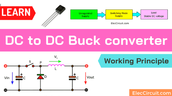
The Main Principle of Buck converter
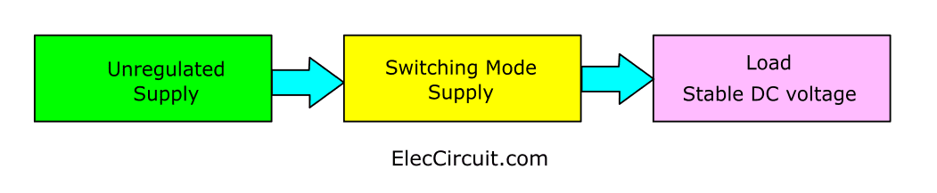
See the simple block diagram below. Most buck converters operate as part of switching-mode power supply circuits. Its input is a DC-unregulated supply, and the output is a lower DC-regulated voltage that is stable to load.
Next, let’s learn about the Basic Step-down Voltage Switching Mode Supply or Buck Converter Block. It has a few components. But how is its output current increasing?
First, understand all the main variables:
Vin is an input voltage in the United States, and “Uin” in European countries.
Vout is an output voltage in the United States, and “Uout” in European countries.
Simple components
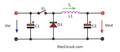
This circuit consists of only four main components, which are:
C1 is the input capacitor. C2 is the output capacitor. They are basic electronic components that we use very often and are very familiar with. They store electrical energy and release it in the same polarity.
S1 is a switch; in the real circuit, we will be using a transistor or MOSFET. It will turn on and off the Vin periodically, like a knife that will cut electrical energy into parts.
L1 is a coil or an inductor. It is an essential component; almost all the switching regulator circuits need it. It works similarly to a capacitor in that it can store energy and release it. But it works a little differently.
When we were children, we liked to play with water balloons. At first, it was difficult to fill the balloons with water. Because the balloon resists being stretched by water filling in. But as the water kept flowing in, it became easier to fill until it was full. And when you stop adding water, it will flow out until it is empty.
A balloon is like an inductor, but instead, it is made from a coil of conductive wire. And as for water, it will be electricity.
At the start, it will resist electric current. But as time passed, the electric current could flow through it better and better. Until almost equal to normal electrical conductors. At the same time, it will create an electromagnetic field.
When we stop powering it, this electromagnetic field will remain for a while and then gradually collapse, causing an electric current to flow back out in a reversed polarity from the original.
D1 is a diode that works like a one-way water valve, setting up the water to flow in the desired direction. In some cases, they can work together to increase the amount of water. For example, draw excess water back for use again. In electronics, it’s the same way. With the help of a diode, we can apply the excess current to increase the output current.
Step-by-step working process
Next, let’s learn how it works. See the block diagram below.
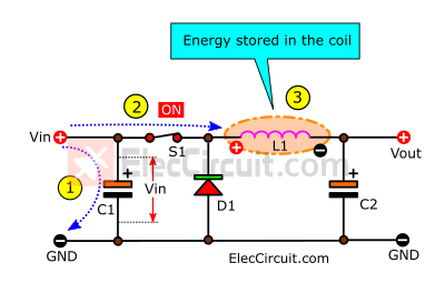
(1) The Vin charges the C1 capacitor until it is full. So, its voltage is the same as that of the power supply (Vin).
(2) The switch (S1) turns on, closing the circuit. It causes the positive voltage to flow into the circuit.
(3) This positive voltage drops across the coil (L1). Because now the Vin is greater than the Vout. The current flow through the coil increases at a linear rate. So, there is energy stored in the coil (L1), and an electromagnetic field radiates from it.
But no current flows through D1 because now it is reverse-biased.
And when L1 reaches its saturation point, the current will flow through it like a normal conductor. So it can charge C2 until it is full as well.
Then, see the next block diagram below.
(1) S1 turns off or opens the circuit, causing no electrical energy to flow into L1 anymore.
(2) But the electromagnetic field around it began to collapse. Causing an induction and releasing an electric current in the alternated polarity from the original.
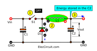
The D1 is now forward-biased, so the L1 current can flow through D1 to GND. Now that L1 and C2 are parallel, the L1 currents add up to the energy already stored in the output capacitor C2. This causes the current at Vout to increase for a moment. However, the current at the coil decreases linearly until it is re-energized by the Vin again.
So as the switch (S1) turns on or closes the circuit, it causes the positive current to flow into the circuit again. The whole process is the same. This whole process causes the output voltage level to be constant and able to supply the load continuously.
Does it start to get complicated? See the simpler power supply circuit
The big problem is the difficulty in controlling the switch (S) in a way that will give us a higher current at the output. There are three modes of current that flow through L1, as shown in the graph below.
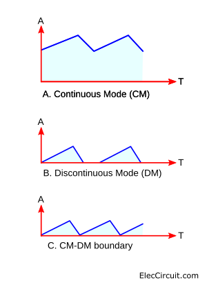
(A) Continuous mode (CM) – When the rate of switching is sufficient. The current is at its lowest point; it will not reach zero. Causing a continuously high current through L1.
(B) Discontinuous mode (DM) – But if the S1 switches on and off too slowly, it will cause the current in L1 to drop to zero in each cycle of operation. This causes the current from L1 to have low efficiency.
(C) CM/DM boundary – In this mode, the switch turns on immediately if the current of the coil drops to zero.
Example circuits
I see that you are sleepy because of reading boring principles, as am I.
But now that we have learned about those principles, we can move on to making a real circuit out of them. And I have picked out a few for you to try making down below.
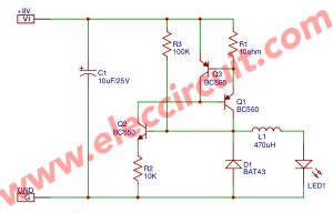
- 5V Switching Regulator Circuit using transistors
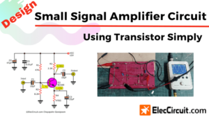
- Switch mode LED driver circuit (Saving energy)
- USB 5V to 12V DC-DC Step-Up Converter circuit
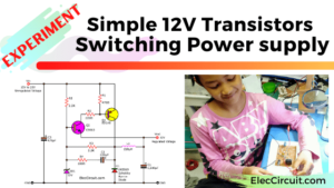
- Simple 12V transistor switching power supply
- 1.5V to 5V boost converter circuit for microcomputer
- 5V to +/- 12V boost converter circuit or higher using transistor
Conclusion
Controlling the switch on or off uses many very complicated theories. But in actual use, it is not necessary to use all the theoretical principles.
Since each circuit may use only 1 or 2 theories. So, we should choose to study only theories that we use often. After that, if other circuits require them, you can study further.
It is normal if you (including my children) do not understand these principles. But we believe that when you handle and practice it, you will be able to solve those problems perfectly. These circuits may be keys to your problems that you may yet to know.
Let’s make these:
- 5V 2A Buck converter circuit using KA34063
- Experiment of 5V Buck Converter Circuit Using Transistors

Related Posts

I love electronics. I have been learning about them through creating simple electronic circuits or small projects. And now I am also having my children do the same. Nevertheless, I hope you found the experiences we shared on this site useful and fulfilling.
Reads like it was written by a brain damaged AI
Hi,
Thanks for your visit our site. Oh! Yes his English quite poor. But try to improve it and he just rewrite it.
I like you, I know you are kind person. Please read it again he are not AI. He is my great dad. Thanks 🙂
that’s great and usefull.
i undrestand completly switching power after 6 years with your post
sory i’m not good at english
thanks a lot
Thank you very much. who have followed us for a long time.
I’m just about to learn it. My dad wanted to make it easier.
Next, I’m going to build the circuit more seriously.
I hope you will follow. 🙂