We are experimental to create a simple counter circuit today, is a 2-bit binary counters.
Which consists of the gate and flip-flop both of TTL-IC type. We use the ICs are NAND Gate number: SN7400N and the flip-flop No: SN7473N, which consists of JK-FF two pieces. We use only one at a time, so can try it on the counter.
Experimentation
– Build circuit as Figure 1. The NAND Gate 2 pieces in IC-SN7400N connect as RS-FF(a flip-flop) for one pulse when we press switch one time.
For JK-FF both in the IC-SN7473N that, We will use as T-FF, with connections pin J, K and CLR pin as marked “1”, and then pin CLR(Clear) is the flip-flop reset pin to output Q in the “0” status with Do not sign up with my JK and CK.
You need to be careful about using the power supply pin VCC and GND of the IC. Because is different from the IC that we used, are the VCC: 4 pin and the GND: 11 pin.
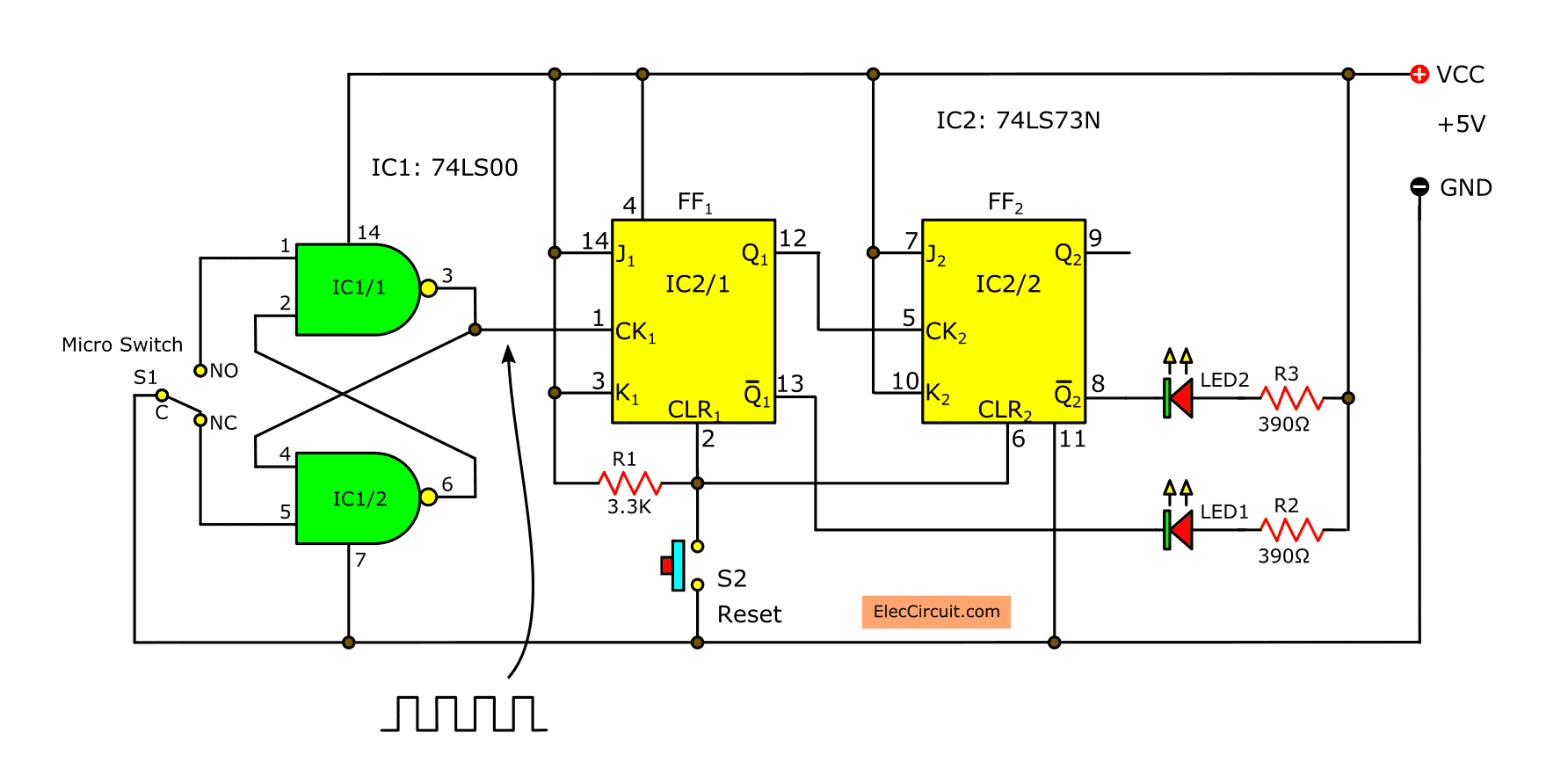
– When the Circuits is complete and then turn on the power supply, the LED may be some that it is in the “set”. To press switch SW2 to reset both flip-flop in reset state (Q1=Q2= “0”) the LED off, Because when Q1=Q2=”0” will be Q1= Q2= “1” Therefore, no current flows through the LED’s.
– Next experimental press switch SW1 once, LED1 will be lit. Press S1 for the second time to see LED2 is lit, while LED1 extinguished. If you press it a third time to see the two LED lights. Also, if you press the switch for the fourth time, LED and two respectively, back to start. If you continue to press the switch, the LED light is the order, the same as the first four.
– The LED lights up to show that it does, output Q of the T-FF is “1”. If LED off indicates as “0” This experiment was a 2-bit binary counters so that counters pulse maximum of 4 goals.
– However, from this experiment will be a bit lower for Q1, Q2 as the main bit of the binary number. When counts second is to carry on from Q1 to Q2, by observation of the sequence of LED1 and LED2. If the counter circuit has Quantity bit or Quantity of flip-flop is more, we will see a reduction to the next principle. 4,8,16, … and so on.
The 2 bit binary counter circuit using CMOS
– We come to a 2-bit binary counter circuit, another experimental one. This is a CMOS integrated circuit, and the Circuits is slightly different from the first Circuits.
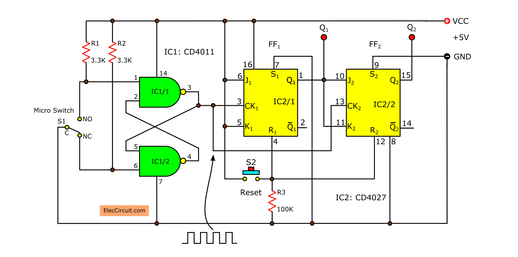
– Circuits shown in Figure 2, using the IC MC14011 B and MC14027 B, which is Circuits very similar to the Circuits in Figure 1. The difference here is that, pulse signal from the RS-FF pulse CK1 and CK2 terminals are connected together, and Q1 is connected to the terminals J and K of FF2.
Thanks: Photo CMOS Logic ICs
The FF1 and FF2 as this will make a T-FF FF1 to accept pulse all time because both J1 and K1 are “1”. While FF2 will to accept pulses when J2 and K2 and Q1 is “1” only, indicating that Q1 will signal each time a pulse comes, the Q2 will be the only time of Q1. = “1” only.
then press switch SW2 for reset flip-flop before, and then so press SW1 for entering puse into this circuit, uses logic probe check at Q1 and Q2, will see that Q1 and Q2 changes same as the first experiment show that the 2-bit binary counter circuit as well.
The counter circuit that uses connection of the pulse signal into CK terminals of every flip-flop in this circuit we called that “synchronous” Which has the advantage. Working properly at all times, even at the pulse frequency is high. Each flip-flop will accept the pulse signal immediately with no time delay.
For connection, the first counter circuit that bring the output of first flip-flop to the CK pin of next flip-flop there will called that “ripple counter”. Which really simple but Plus it came to pass, each flip-flop, from the front to the back of the wave, the pulse frequency is very high, and this wave of change can not to keep pace
Related Posts


I love electronics. I have been learning about them through creating simple electronic circuits or small projects. And now I am also having my children do the same. Nevertheless, I hope you found the experiences we shared on this site useful and fulfilling.