Imagine you want to listen to great music in your room. You may have many choices. Before seeing others. Let’s see this 30w amplifier circuit. Why you should see it?
If your small room is small. And, you like to listen to great music that nice quality, low noise, full option adjusting. Also, it is cheap and easy to find the parts in any store.
Download This Post as a PDF and all PCB layouts
What is more?
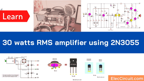
I often recommend this project. It is one of the timeless amplifiers. With the power of 30 watts RMS amplifier circuit diagram with PCB. It is suitable for you.
In the circuit uses all transistors like 2N3055 and small transistors.
So, low noise and easy to buy them. Though it is a too old circuit. But we want to return conserve valuable antiques.
If we will compare it with others in the same watts. This 30W amplifier is the best, quality sound. Because it is an OCL amplifier. So, responds to bass and treble well.
Thanks, designer, he designs the circuit is really perfect.
Read next: Video amplifier splitter using transistor
How this project works
As will see Figure 1 that they composed of the most 2 parts are:
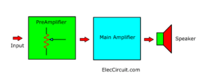
- The tone control circuit
- The main amplifier circuit
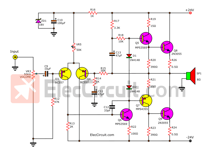
The figure 1 circuit of the project
To begin with, the tone control section is determined as the feedback tone control type. Which is popular extensively at this time.
Then, you can adjust the bass sound up to +18dB at frequency 100Hz. And, can adjust the treble sound up to +18dB at frequency 10Khz.
Read also: TDA2020 OCL HI-FI Power Amplifier, 20W to 80W
In the power amplifier circuit, you will see that the input circuit is connected to the differential amplifier type.
To control the output of this circuit is zero volts. By using the feedback at the base of Q4 through the R16.
The gain of this circuit is R16/R15. Then, the signal from the collector of Q3 will pass to the base of Q6. Which, Q6 acts as pre-driver to amplifiers signal to the driver circuit that consists of Q5, Q7.
In setting, the last output section is determined by forming the Quasi-Complimentary. So, the saving than the direction the pair complimentary. Then, we use both 2N3055 transistors are pair output Q8, Q9.
See other 30W amplifier circuits list
- TDA2030 transistor amp circuit with PCB
- LM1875 Datasheet 30W HIFi audio amplifier circuit
- Tri Band Amplifier Circuit Project with Crossover network
How to builds the circuit
- First of all, Build the PCB as Figure 2 and assemble correctly the components layout for the PCB as Figure 3.
- Second, does not connect the power transistors Q8, Q9
- Third, use the voltmeter set range DC Volt is 50 volts and then measures the voltage across between the output or speaker terminal compare with the ground. But you should connect the short-circuit between the input and ground before.
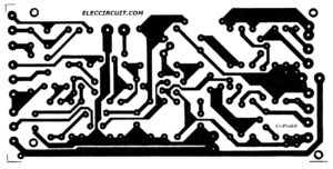
Figure 2 Actual-size, single-sided PCB layout for the circuit.
Here are a few related articles you may want to read:
- Transistor Crystal Oscillator circuit ideas
- What is switching power supply vs linear, how does it work?
- Transistor stereo bass booster
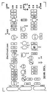
Figure 3. Component layout for the PCB
- Next, connect power to this project Observed meter needle that reverses or not, if error to must switch the test leads immediately.
- Then, adjust the potentiometer VR5 until the voltage is zero volts. You should reduce the range of meter to lower respectively, until the lowest, with the certainty that can read really is zero.
Related: NE5532 Pinout Datasheet Dual low noise op-amp - Then, insert correctly the output transistor to this project.
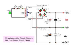
- The main DC power supply of this project is + 24 volts up to 2 amperes. So, we use the transformer that has a secondary coil is 18-0-18V at 2 amperes. Next, passing the bridge rectifier circuit and filter capacitors. Then, we will have the results as the DC volts + 24 volts for this circuit.
Read other sites: 30 Watt Amplifier Circuit using Transistors - Next, The filter capacitor- should have over 4700uF 50V as characteristics the standard power supply circuit that uses in normal.
Main Amplifier
For those who only need the main amplifier or final amplifier circuit, see the schematic below.
Selecting and substituting components.
I believe you understand basic equipment usage and can do it. We can use various components of the 30watts amplifier circuit.
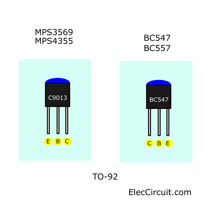
The Small transistor. Look at Their Pinout of TO-92:
Sometimes, you may not buy MPS3569 or MPS4355. You can use:
- C9013 is instead of MPS3569
- C9012 is instead of MPS4355
- BC547, BC548, BC549, BC546
- BC557, BC558, BC559
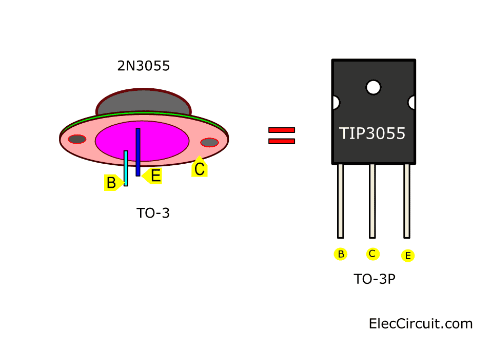
Power transistor 2N3055. Look at the pinout of the TO-3 transistor.
If you want full power output, cheap. You should use a 2N3055 NPN transistor. But it may be better if uses TIP3055(TO-3P). We easily install it on the heatsink.
Listen to a lower volume. But still, sound good.
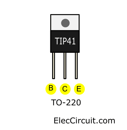
If you especially like treble or mid-range music. You can switch to a smaller power transistor instead of 2N3055. Like TIP41 with the shape of TO-220.
Read next: Learning electronics for beginners for review.
Detail of parts list
- Q1, Q2: BC547, 45V 100mA NPN Transistor
- Q3, Q4: BC557, 45V 100mA PNP Transistor
- Q5, Q6: MPS3569 or C9013, 40V 0.5A, NPN Transistor
- Q7: MPS4355 or C9012, 40V 0.5A, PNP Transistor
- Q8, Q9: 2N3055, 100V, 15A, 115W, >2,5MHz NPN transistor
- D1, D2: 1N4148, 75V 150mA Diodes
- ZD1: 18V, 1/2W Zener Diode
Linear Potentiometer
- VR1, VR2, 100KB
- VR3, 50KACT
- VR4, 100KMN
- VR5, 50K PRESET
Electrolytic Capacitors
- C1, C2, C6, C8, C9: 10uF 16V
- C7: 100uF 10V
- C10: 100uF 25V
- C11: 47uF 16V
- C13: 47uF 25V
Polyester Capacitor
C3, C4: 0.047uF 50V
C5: 0.0022uF 50V
C12: 33pF 63V
Recommended: What is capacitor? Principle working, types and how it works
1/4W + 1% Resistors
R1: 560K
R2: 220K
R3, R10: 4.7K
R4, R5, R6: 8.2K
R7, R17: 3.3K
R8: 100K
R9: 470K
R11, R14, R16: 1K
R12: 47K
R13: 2K
R15: 56K
R18: 10K
R19, R22: 15 ohms 0.5 watts
R20: 100 ohms 0.5 watts
R21, R23: 390 ohms 0.5 watts
R24, R25: 0.5 ohms 1 watts
Power supply parts list
(As the circuit diagram above)
- C6, C7: 4,700uF 50V, Electrolytic Capacitors
- C8, C9: 0.1uF 50V, Ceramic Capacitor
- T1: 117V/230V AC primary to 18V-0-18V, 2A secondary transformer
- D1-D4: Diode 5A, 100V
- S1: ON-OFF Switch
- F1: 0.5A Fuse
Download This!
All full-size images and PDF of this post are in this Ebook below. Please support me. 🙂
Check out these related articles, too:
- 30W to 60W RMS OTL integrated audio amplifier circuit
- 50W OCL main amplifier using LF351-2N3055-MJ2955 PCB
- LM3875 Gainclone Amplifier circuit | Stereo 56W
Related Posts

I love electronics. I have been learning about them through creating simple electronic circuits or small projects. And now I am also having my children do the same. Nevertheless, I hope you found the experiences we shared on this site useful and fulfilling.
Hola!
El circuito dice unos valores para R17 a R23 y en la lista de materiales dice otros valores para estas resistencias.
Que valores son los correctos?
Salu2!
thankz bro
Hello Mark,
Thanks for your feedback.
Does it work as a eletric guitar amplifier? Thank you.
@Gabriel: since the audio output from the guitar is so low, you’re going to need more gain. Slap a pre-amplifier circuit to the input of this stage, and you’ll be good to go.
is this amplifier work if i have 12 volts battery ??
please give the answer ??
Hello Shoaib,
Thanks for you vist. I like a your question. Let me share to you.
This circuit can be used with only 12V battery. You need helping with DC To DC converter circuit. It will increase voltage from 12V to Dual 24V +/-
See: https://www.eleccircuit.com/dc-to-dc-converter-12v-to-40v-using-lm3524/
or
https://www.eleccircuit.com/dc-converters/
sir what is the replacement for the transistor mps4355 and mps3569
Hello pogi,
Thanks for you visit. Please see in text again. You will get the answer.
I need circuit diagram of NO55 & PO55 transistor amplifier circuit diagram with PCB.
still schematic . I have one .
Hello babu.
What do you mean? Have you this circuit?
I love this circuit, too.
Hello Biman,
Thanks for you visit my site. Do you want NO55 & PO55 transistor amplifier circuit diagram.
Now, I do not have this circuit. I’m sorry. Please back to see again later.
Thanks
Apichet
# From email
Dear Manager, hello my friends;
>
> I bought something from your site (circuit 2) 30 watt osl amplifier
> 2N3055 my mount, failed in
>
> 4 th attempt… Then have the same values (circuit-1) I found it from
> a different site. I will not make the circuit I bought from your
> store. I only want to make the preliminary amplificator. I just want
> to make the output floor like circuit-1.
>
> Problems:
>
> * 18 Volt 5 Amps (zd 1) in both circuits short circuit burn due to
> excessive heat.
> * While in circutor1 Q7 baze input collector goes to 2N3055 base
> enter, in circuit-2 the same transitor emiter exit goes to 2N3055’s
> base ?
> * I applied 78L18 white circuit-1 to circuit-2 again 18 V zd1 and
> 78L18 burned again due to heat.
>
> * In the description that you gave it’s said that “At first,
> power transistor does not connected. The enterences do short circuit.
> In 60 Volt set the OUTPUT connects. Voltage is given to circuit. Until
> the voltage shows 0, 50K trimpot and voltage are set. ” I couldn’t
> make it. May I ask for your help.
>
> Those friends who had done this circuit can help me please?
Hello mehmet nuri kaynar,
Thanks for your visit to my site. I am happy that you feel interested in this circuit.
Let me share with you your question.
1. ZD1 is too heat. Please check R16 If we put low resistance. The higher current to ZD1.
2. Yes, This circuit worked. I made it long time ago.
3. I do know about 7818. If it is hot. Its output may be short circuit.
4. Yes, in setting please in text again.
I believe in you. You can do.
Nice sound! I made it done.
Hello Jisy,
Thanks for your feedback.
What is higher watt than this?
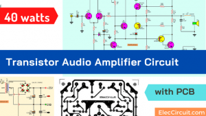
Thanks again. Please look at https://www.eleccircuit.com/40w-amp-ocl-2n3055mj2955/
It is all transistors amplifier circuit. Do you like transistor circuits?
Hi! I am trying to build this circuit, but i can not understand something. “measures the voltage across between TP points compare” What does TP points-mean? Where are these points on schematic?
Thanks for help.
Attila.
Hi Attila, My friends,
I am happy that see your text. I love this amplifier circuit.
I am sorry TP = Output or speaker terminal.
Set to dial of the Digital Multimeter(DMM) to DCV or Analog meter 50V range. Measure voltage between the output or speaker terminal and the ground.
I hope you will enjoy your amplifier.
Have a good day.
Apichet
Hi! Now it is clean, thanks for help!
With pleasure my friend. I really want to see your amplifier. It must surely make a smile for everyone.
Hello I have a question what do you mean by “But must short circuit for the input to the ground before” ?
HI! I want to make this project but I have 2 questions.
1. The transformer 18-0-18V at 2 amperes is for stereo amplifier or mono (and for stereo we need 18-0-18V at 4 amperes)?
2. I want to use only the final amplifier. Can I cut it in C9(+) for input and not use the pre-amplifier and zd1+C10? If yes the transformer must be at 2 amperes or less?
Hello George A,
1. Yes, 4A for stereo amplifier and 2A for mono. Or some friend uses 2A for stereo but he turns the volume in half only.
Hello George A,
1. Yes, 4A for stereo amplifier and 2A for mono. Or some friend uses 2A for stereo but he turns the volume in half only.
2. Yes, you can use it as the main amplifier by cutting the pre-amplifier circuit away. But you should put C9 to block any DC signal.
But you should still place ZD1 and C10, they keep a stable voltage in Q3 and Q4.
Have a great day.
Apichet.
Thanks for reply!
So, 24-0-24V 4A for stereo with 2N3055 and output 2x30W.
If we use TIP41, for stereo, without the preamplifier what voltage and amperes we need, and how many watts we have in output.
And something more. Can I use S9012 for C9012?
Please reply!
“Hello,” my dear friend,
Yes, it powers about 30 watts and has excellent sound in a small room.
Yes, you may still place a dc regulated power supply circuit (ZD1 and C10). Sorry for my wrong advice last time.
Yes, you can use C9012 or S9012 pinout it is E-B-C.
Have a good day.
Apichet
TIP41 has the same output power with tip3055 and 2n3055?
And TIP41 requires 24v-0-24v 4 amperes like 2n3055?
Hi, my dear friend,
In my experience, the 2N3055 (genuine) is the most efficient, and durable, and has an excellent mid-range frequency response. If you use the TIP3055, it’s about the same. Look in the datasheet, it has the same specs, but for the TIP41 it’s slightly lower. If we listen to soft music in a small room, there is almost no difference.
Thanks,
Many values of resistors are different between of diagram and the description. I think, it looks the correct values is of the schematic. Am I right?
Various devices can be flexibly changed. Please don’t worry. Sometimes it’s fun to experiment with modifying transistors and listen to different sounds. Good day!
You confused me a bit.
When I wrote to you “I want to use only the final amplifier” the first time you replied to me you wrote:
– “You should still place ZD1 and C10, they keep a stable voltage in Q3 and Q4”.
And the second time you wrote me:
– “Yes, you may still place a dc regulated power supply circuit (ZD1 and C10). Sorry for my wrong advice last time”.
What did you mean? Can I replace “ZD1 and C10” with something else like a dc regulated power supply circuit with LM350 or LM338 or 7818?
Please reply me.
Hello, dear friend!
I apologize for the confusion. My English is quite poor.
Okay, I will redraw just the final amplifier circuit for you.
https://www.eleccircuit.com/the-30-watts-rms-integrated-amplifier-projects-using-cheap-transistors/#Main_Amplifier
“You should still place ZD1 and C10, they keep a stable voltage in Q3 and Q4”. It’s correct.
Both ZD1 and C10 are the simplest regulated power supply circuit for this amplifier. It is enough for this amplifier. The other regulator IC is not needed.
However, you can experiment with it if it interests you. But I haven’t tried using an LM7818 for this circuit yet.
God bless you.
Apichet
I think that the base of Q9 (2N3055)
must be connected with the connection
at R23 (390 ohm) and the collector Q7 (MPSA4355).
PS: The last drawing is correct ! 😃
Hi,
You are a very lovely person. Thanks for visit our site.
My dad used to build this circuit when he was a young
and he said it sounded great, so I wanted to build one for my guitar.
I’m waiting for my brother who designs pcb boards.
It should be of better quality than before.
When it’s finished, I’ll share it with you.
Thank you for following. 🙂
Some truly nice and useful information on this site, likewise I conceive the design has fantastic features.
Hi,
Thanks for your feedback. 🙂
Hi, Can we use 15-0-15 2A transformer ?
Hi,
Thank you for answering your question.
My dad commented that it might work.
It works but the sound may be quieter because the pressure is low.
You may need to change ZD 1 to 15V.(If the sound is very soft)
Hope you have success with this circuit. 🙂
Heya i am for the first time here. I found this board and I to find It really helpful & it helped me out much. I hope to offer something back and help others such as you helped me.
Thank you for visiting our website. My dad and I will try to learn more and that experience to you. I hope you will continue to follow us. 🙂