This is TDA2030 subwoofer amplifier circuit that uses the integrated circuit. and Transistor BD249 or TIP31 or TIP41 or C1061 and BD250 or TIP32 or TIP42 or A671. It is a nice circuit and easy to use.
We design a circuit with TDA2030A as a driver to power transistor output to apply output up to 30 watts. Then take both circuits to bridge together, makes we have the power output up to 4 times and have even maximum power output is 200 watts.
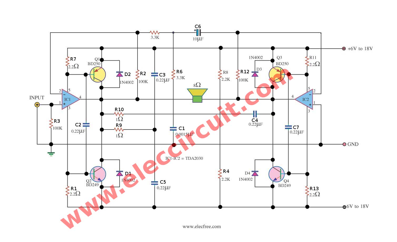
Schematic diagram of TDA2030 subwoofer amplifier circuit
May don’t be defeated because this circuit gives the electric power about 120 W that load 2 ohm. When seeing the circuit will think to use important equipment be. Must use power supply source that is appropriate to +15V and -15V that current 2Amp. Besides should use heat sink at have the size is appropriate IC TDA2030 and Q1-Q4 BD249,BD250 foresee the circuit has already. Build easily must not fine decorate anything.
– The advantage of this circuit, the voltage of the power supply is low (compared to other circuits. Watts are equal in size), so I used the low voltage capacitor, smaller, and cheaper.
– As can be seen from the circuit, we enter a signal input at pin 1 is side single. With pin 1 of IC2 (TDA2030) is connected to ground, And the output signal fed back to the inverting pin (pin 2) of IC2, Allow us to signal with opposite phase, input to the amplifier is one automatically.
How to build
Soldering Electronic Components to the right, onto the PCB as shown in Figure 2. Then install the power transistor to the heat sink. By Vice insulating sheet mica. To prevent a short circuit on the heat sink neatly.
When certain everything must be right, it was the power supply to the circuit, in order to use it, without having to adjust the circuit.
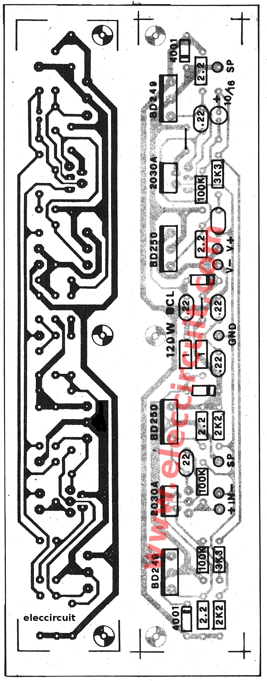
PCB layout and Components layout
Detail of circuits
Q1, Q3: BD250, TIP42, PNP POWER TRANSISTORS(25A,125W)
Q2, Q4: BD249, TIP41, NPN POWER TRANSISTORS(25A,125W)
D1, D2, D3, D4: 1N4002, Diode 1A 100V
IC1, IC2: TDA2030A, 18W HI-FI AMPLIFIER AND 35W DRIVER
R1, R7, R11, R13: 2.2Ω Resistors 0.5W
R2, R3, R12: 100K, Resistors 0.25W
R4, R8: 2.2K, Resistors 0.25W
R5, R6: 3.3K, Resistors 0.25W
R9, R10: 1Ω, Resistors 0.25W
C1: 0.0015μF 50V, Polyester Capacitor
C2, C3, C4, C5, C7: 0.022μF 50V, Polyester Capacitor
C6: 10μF 16V, Electrolytic Capacitors
Note: Transistor BD249 or TIP31 or TIP41 or C1061 and BD250 or TIP32 or TIP42 or A671. It is nice circuit and easy to use.
You may like these circuits, too.
- How to use LM386 audio amplifier circuit
- TDA2030 Bridge amplifier circuit
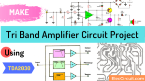
- Tri Band Amplifier Circuit Project with Crossover network using TDA2030
Related Posts


I love electronics. I have been learning about them through creating simple electronic circuits or small projects. And now I am also having my children do the same. Nevertheless, I hope you found the experiences we shared on this site useful and fulfilling.
How to test this amplifier please explain
In description .022uf capacitor but in circuit layout its .22 pls help