4 Simple transistor amplifier circuit
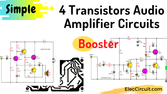
This is a 4 transistor audio amplifier circuit. Which is a 4-transistors complementary push-pull amplifier, that shows the basics of audio amplifier design. Read more
This is a 4 transistor audio amplifier circuit. Which is a 4-transistors complementary push-pull amplifier, that shows the basics of audio amplifier design. Read more
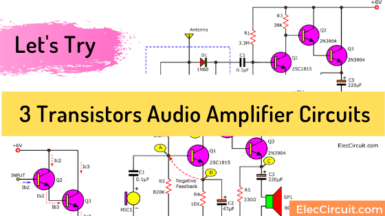
Do you like a transistor? Today I am going to 3 transistors audio amplifier circuits. Why use transistors in the amplifier? Transistors are devices made of semiconductors. It has many benefits, but the most important and common use is to use it as an amplifier. How? Must … follow to see. Although currently, we will … Read more
This is a bass booster circuit that use transistors as base. It is designed to increase a low frequency of audio on cheaper than ICs or normally circuit. Read more
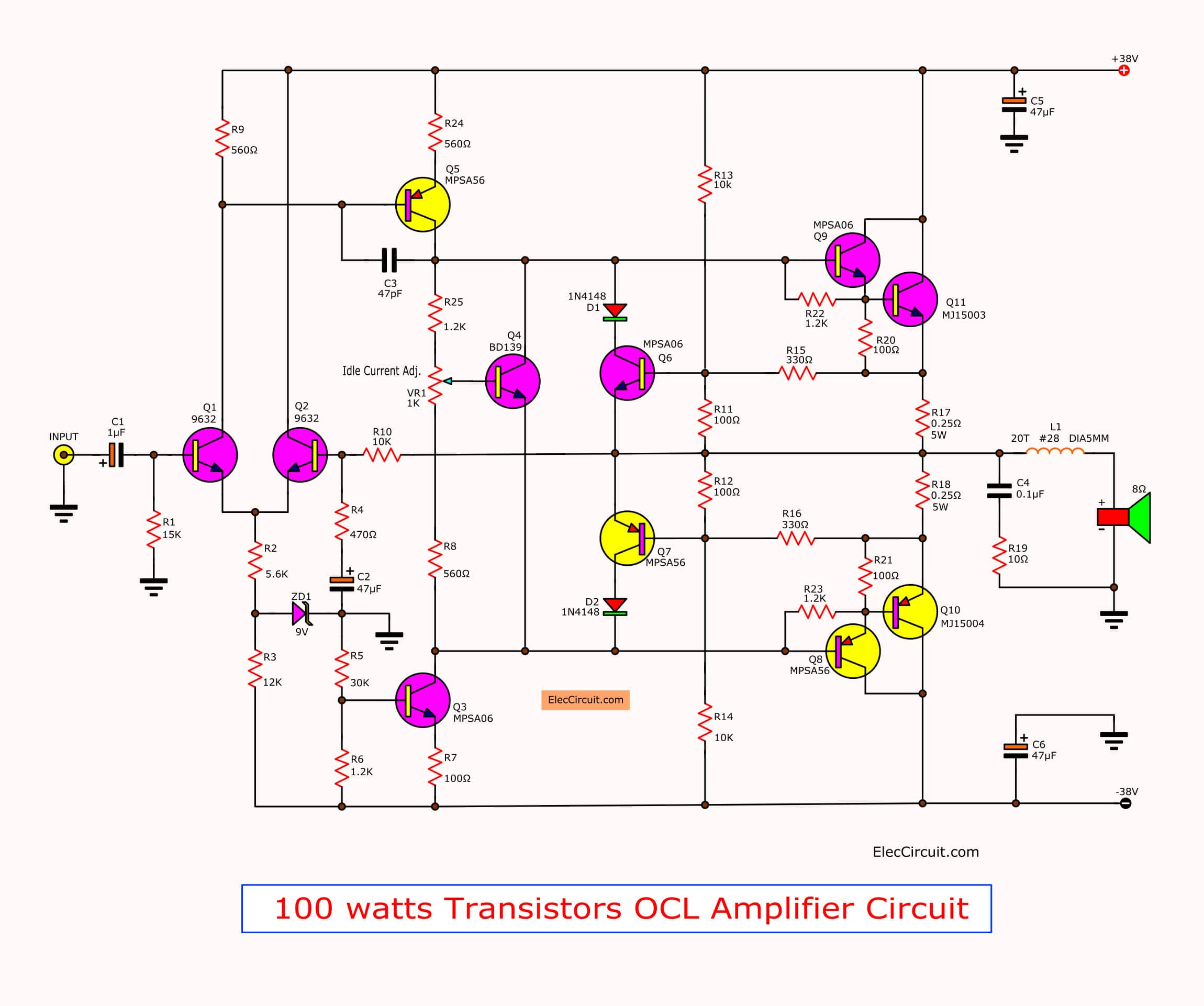
This 100W amplifier circuit by transistors, but very well OCL amplifier schematic.Use transistor MJ15003,MJ15004 as main. Power supply +38V 0 -38V 3A. […] Read more
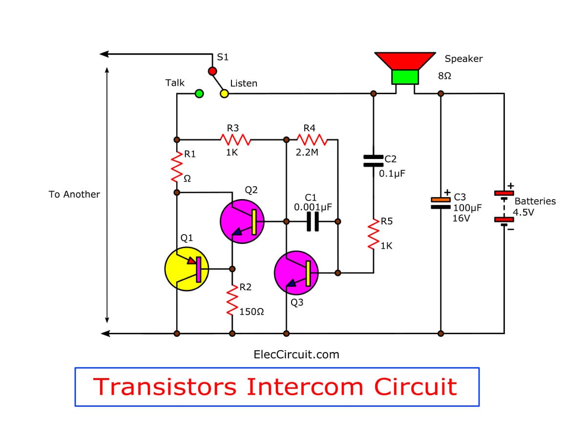
See simple intercom circuit using transistors and a few parts. So easy build and cheaper than ICs. For a small home and learning. Read more