Here is a 555 timer circuit project. You can use it for the snooze alarm with a buzzer. When on-time 5, 10, 15, and 20 minutes. It is easy to make and portable with small PCBs. Also… If you want to control other loads. It is easy with a relay directly. Because the output of 555 has a maximum current to 200mA.
Recommended: How does NE555 timer circuit works
How it works
When we turn on switch-S1 to enter a power supply to the circuit. It will be ready to go.
The parts have a different function.
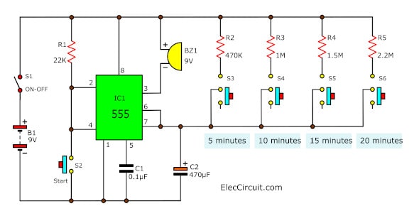
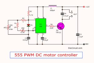
The circuit includes IC1-555 Mono Stable (timer) for the delay.
Switches S3 S6—choose a time as we want
- If turns on S3 for 5 minutes. Then, turn off the S3.
- To turns on S4 for 10 minutes. Then, turn off the S4.
- Next, it turns on S5 for 15 minutes. Then, turn off the S5.
- Last, turns on S6 is scheduled for 20 minutes.
This project uses the principle of monostable multivibrator 555. It works with a delay charge and discharges completely.
When in time that setting. It will send a signal to Pin 3 is low. But can power buzzer-BZ1 beeps out.
The time value is determined by the value R2, R3, R4, R5, and C2.
If you want to set up a long time. It increases the R and C.
The time is short. If it reduced the R and C.
Other: 555 timer projects
How to build this project
First of all, get the components from the list below. This project is very easy. Because of using a few components.
Parts you will need
IC1: NE555 timer IC
C1: 0.1µF 50V, Ceramic Capacitors
C2: 470µF 16V, Electrolytic Capacitors
R1: 22K, 0.25W Resistors, tolerance: 5%
BZ1: 9V Piezo sounder (incorporating 3KHz oscillator)
S1: the ON-OFF SPST switch
S2: Normally open pushbutton Switch
S3 to S6: small SPST Slider Switch
B1: 9V batteries
Wires, Socket IC, etc.
Recommended: How does an SCR work
Then, assemble them on a PCB as the PCB layout and the component layout.
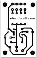
The copper PCB layout
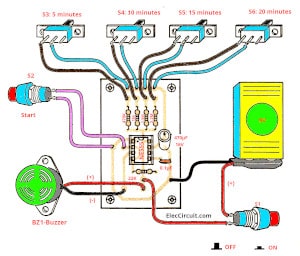
Components layout
Or, If you want to save and quick to build You may use a perforated PCB, too.
But…
You must be careful about some devices with terminals. For example, IC-555, Electrolytic capacitors, and buzzer.
They will are connected to match terminals only.
Note:
This project worked my son test it on the breadboard. Below!
He tests at 5 minutes.
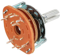
About S3 to S6, the designer wants to use a small switch only. You can use the rotary switch. It is easy, too.
Adding Relay to control more
If you want to control more load. It is an easy way with helping of Relay. Look at the image below.
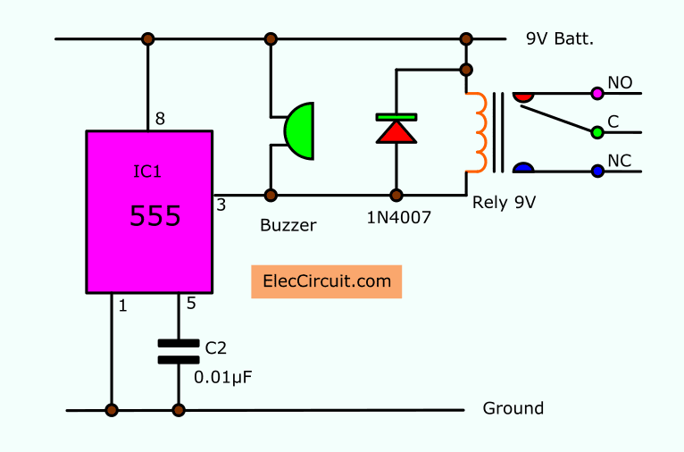
Conclusion
This is a simple universal timer project. You can use a relay to connect with the buzzer. To control other loads that you want.
…
Download This
All full-size images of this post are in this Ebook: Elec Circuit vol. 2 below. Please support me. 🙂
Check out these related circuits, too:
- The simple long duration timer circuit
- CD4060 Timer Circuit 22 seconds to 4 hours
- Simple 555 countdown timer circuit with alarm
Related Posts

I love electronics. I have been learning about them through creating simple electronic circuits or small projects. And now I am also having my children do the same. Nevertheless, I hope you found the experiences we shared on this site useful and fulfilling.
Hi, Midhun
Thanks for your sound.
On the circuit diagram a pin 5 and Pin 1 is placed alternately.
We sorry for this error.
Why pin 5 and pin 1 swap. I saw other 555 circuit, the pin 5 should connect cap. Moreover, if pin 1 and pin 5 swap, can you update the circuit. Many thanks.
Hi,JV
Normally Pin 5 to capacitor and Pin 1 to Ground.
Please look at circuit.
Thank for your comment.
You Could Use A 4 Position 1 Pole Rotary Switch Instead Of 4 Switches..It would Work!!!!
How we make the circuit will buzz every 30 minutes when S6 is turned on.
Dear Admin,
I want to make a timer circuit similar to what you shown here. But I want to connect the timer circuit to my Air Conditioner which is of 1647 Watt.
And I want to make it work for infinite loop, i.e. it switch on for 30 mins then switch off and then again switch on and so on. Please suggest me the required modification.
i did a combination of 555 and cd4047 ic
Hell Char,
Good idea. You made IC555 and CD4047 together. Please share me.
Complete documents and diagrams for a 12 minute countdown timer using 74LS190 and 74LS47 ? Thanks in advance
May I ask how you calculate the value of the R and C based on the wanted time?
Tnx i really enjoyed de 5mins to 30mins timer.may God bless u
what switch we should use??
what switch we should use?
Hi, dp
Thanks for your feedback.
You can normal SPST switch.
wow the timer alarm works
Hi,bee.
I am very very happy that hear you.
Please show projects to us. Your project is best!
not working! the buzzer turns on just after i switch on the circuit! what might be the problem???
Hi tasn,
Thanks for your feedback.
This circuit works please check push bottom switch and circuit parts again.
Hello again! the problem was with my switch S2,i used a SPST instead of a push switch. Now I’ve fixed it and the circuit works!! Thanks!
i want to make circuit but the circuit work after 30 mniut .. this circuit let the buzer work for 30 mniut but iwant to let it start work aafter 30 mniut
admin
please help me out,how should i construct 10minutes timer
i want to turn off my pump after 15 min after i switch on please suggest a modification
hi sir please help me to make power supply 12v which ONtime is 15min and OFF for 30min and repeate this please mail imformation on my id [email protected]
I want a circuit which can switch on a 500watt load for 10 min and then switch off the same load for 10 min and switching on and off goes repeatedly. Thank you
I want to make a timer circuit for my home use submersible pump. Plz help me to make a circuit by which the pump switch offs automatically after 20mins of switch on.
What kind of buzzer do I need (voltage) ?
If I want to use a small round 5v buzzer, what do I need to change ?
Thanks.
Hi sir,i want to turn off my pump after 15 min after i switch on please suggest a modification on my id [email protected]
I try this using simulator but it does’nt work.
please tell me when i start my water pump, how it will turn off ofter 08 min. with out water related circuits {tell me}.
i want to stop my water pump (without water related circuits) ofter 08min. please tell me
@K.venkatarao all you need is a Hall Effect flow switch, connect in series with your level sensor switch configure at AND gate…What you need is to give permissive start to your pump, if there is no water pump control system must not start or have to stop if water for priming is not available..Correct me if I am wrong..
Sir,
Do you supply kits also
Hello Bhatia,
Thank you that you are interested this circuit.
I am sorry. I cannot sell a KIT for you.
But you can use other way to do with bread board. It is easy too.
When there is any progress Please let me know here.
hello! may i see the breadboard please?
Hello dcas,
Thanks for your visit. Do you want a component layout on the breadboard?
It is easy, you can do it.
it cant work
can you help me with these
Hello Andre,
I am sorry to hear that.
Yes, I will help you. Please tell me. how is it?
You may test it on the breadboard first.
I’m having trouble switching the legs of the IC.
I will wait and hope that you will finish this circuit.
Thanks