5-minutes Power Off Delay Timer Circuit
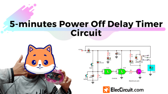
Want to have longer lighting with the original battery? Let’s learn the concept and design of the power off delay timer circuit in a simple way. You may apply it indefinitely. Read more
Want to have longer lighting with the original battery? Let’s learn the concept and design of the power off delay timer circuit in a simple way. You may apply it indefinitely. Read more
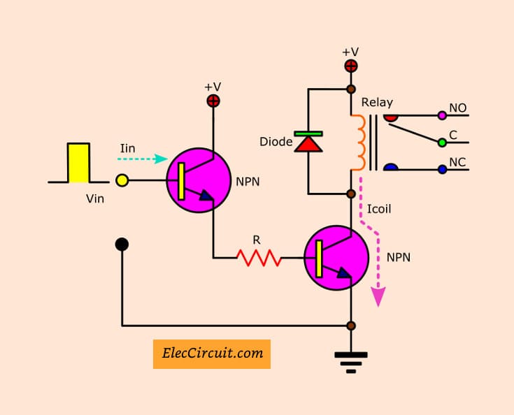
How to control a load with a digital circuit like Arduino? A transistor relay circuit may be answered for you. The output pulse from the digital circuit to biased the transistor is ON. Then, it drives the relay as a switch ON-OFF. To power to any circuits or external devices. Basic Application Relay The Controlling … Read more
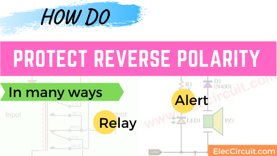
This circuit is an automatic reverse polarity switch. If we apply DC voltage to any electronic circuits in the wrong polarity. It can be caused by too much current. You must waste time to reverse the new terminal. If your circuit is important, let’s build this project to your life will better. Automatic Reverse polarity … Read more
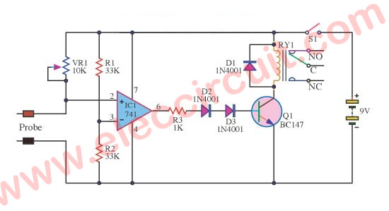
Simple ideals of soil moisture detector circuit projects, can alarm with LED and buzzer, and controller as water for plants Read more