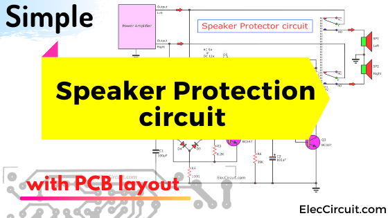
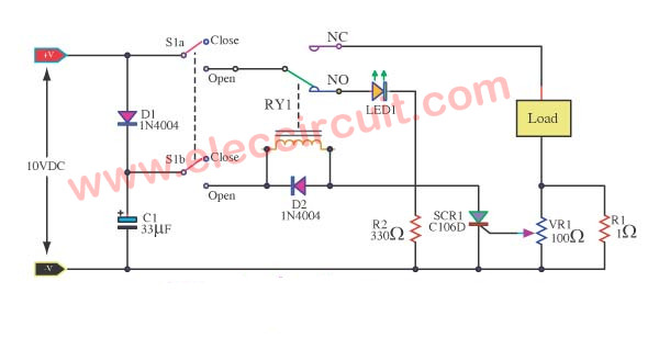
Simple speaker delay circuit
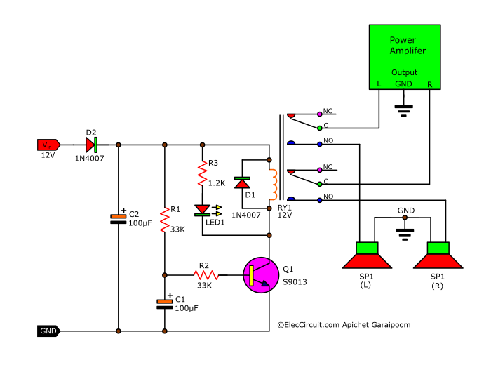
I recommend you to make a Simple speaker delay circuit. Imagine you finished a normally OCL power amplifier. Every time you turn on within the first 3 seconds. You may hear sound “tlub…” on a loudspeaker. You feel annoyed that sound, right? Important, this sound is a high spike voltage. It can damage the loudspeaker. … Read more