Make Cricket Buzzer Generator circuit using LM324
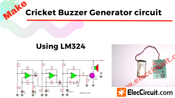
The cricket sound effect circuit which is an another Sound effects generator byLM324 op-amp and emit by a buzzer. And they have sound similarly the cricket Read more
The cricket sound effect circuit which is an another Sound effects generator byLM324 op-amp and emit by a buzzer. And they have sound similarly the cricket Read more
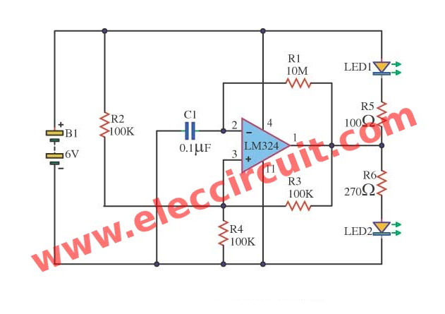
This Op-amp LED flasher circuit , that interesting. By it will wink to alternate between LED the red and LED the green. This circuit can work with IC LM324, […] Read more
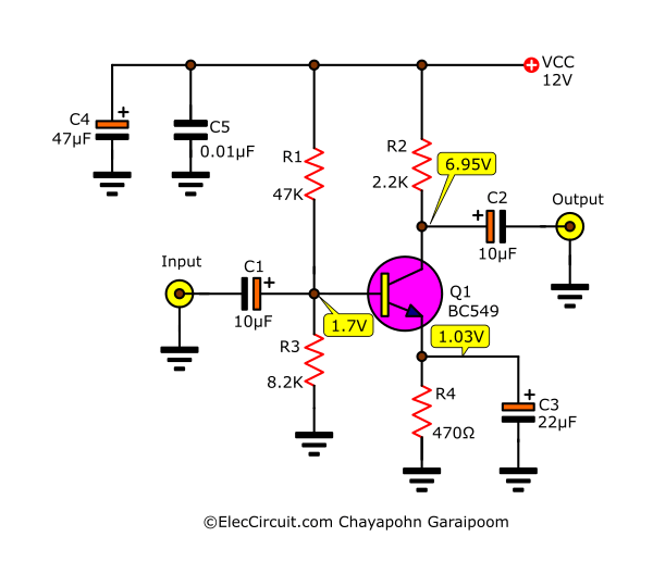
This is a low pass filter subwoofer using IC 324 and some other components. Read more
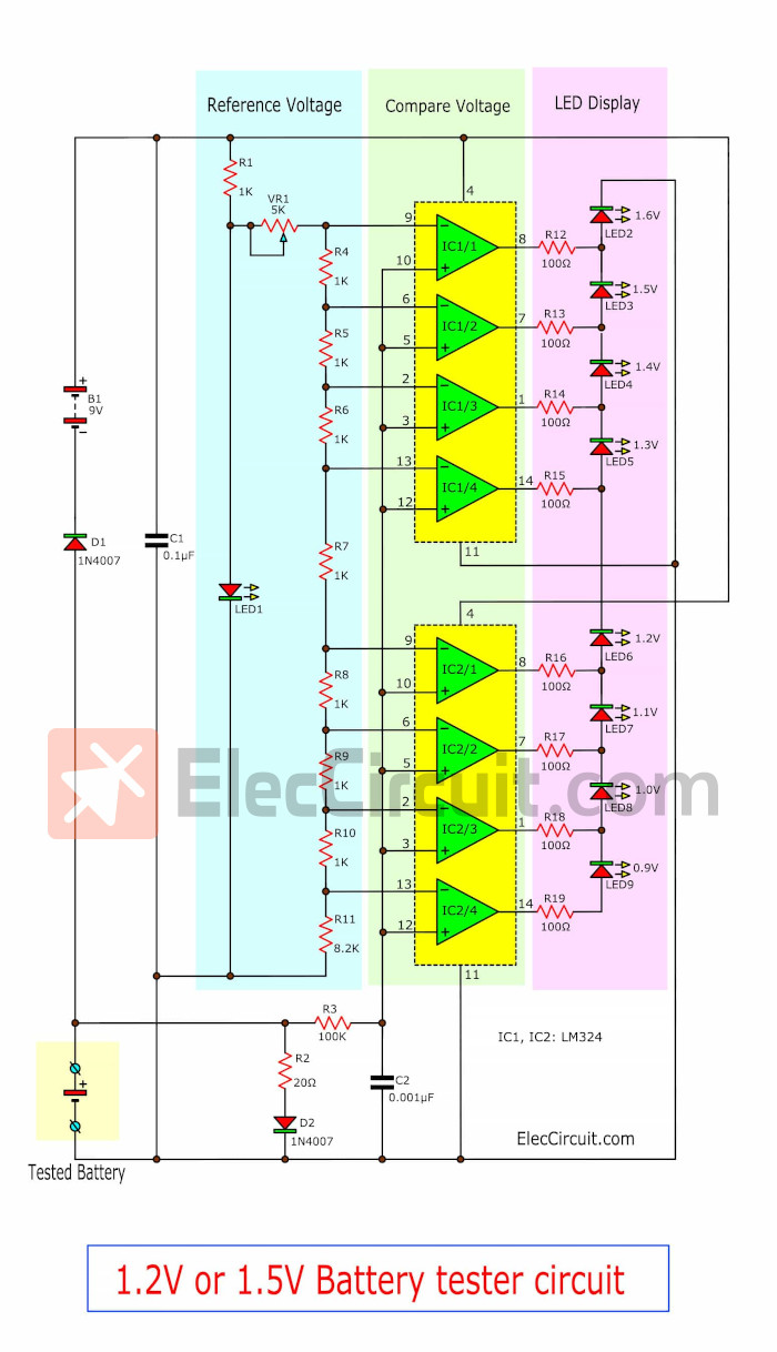
This fine 1.5V battery tester circuit using LM324, Can measure the voltage of the 1.5V battery AA or AAA. As decimal point. Easy to use by LEDs display Read more
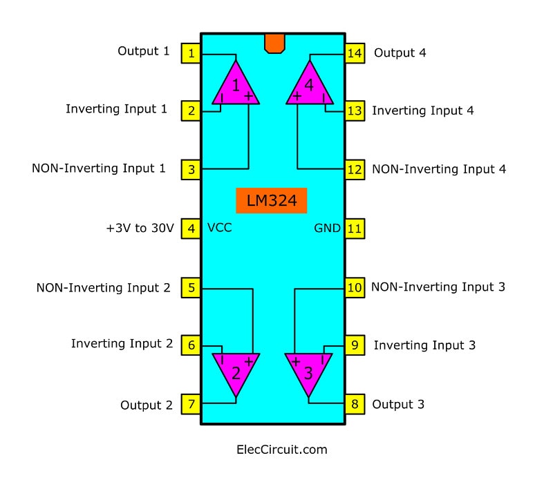
The LM324 circuit is high popular, in many circuit diagram,package of four (OP-AMP) The power is single-polarity positive- negative, very wide range. […] Read more