Do you need to build a variable DC power supply? There are a lot of choices for you. However, many people choose LM317 as their first choice, me too! Because It has high efficiency, is easy, and is cheaper. We can use it instead of the 1.5V, 9V, 12V battery, and others as we wish.
Is it real? You will find out how, below.
LM317 Datasheet in short
This is an adjustable 3-terminal positive voltage regulator, capable of supplying more than 1.5A of load current, and an adjustable output voltage: 1.2V to 37V range.
Also, LM317 has an internal current limiting, temperature detects shutdown, and safe area compensation.
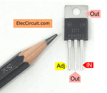
LM317 pinout
If we do not know the position of each lead(leg), we will be unable to use it properly.
Let’s take a look at its pinout below.
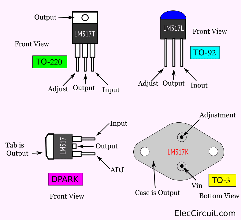
Illustrate connection of various LM317 Pinout:
- LM317T on TO-220: output 1.5 A
- LM317L on TO-92: output 100 mA
- LM317K on TO-3: output 1.5 A
- LM317 on DPARK: output 1.5 A
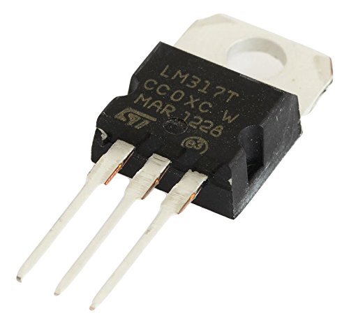
The most used package is TO-220, which looks similar to the MJE3055 transistor.
Basic Features
- Output current in excess of 1.5 A
- Output-Adjustable between 1.2 V to 37 V
- Internal Short-Circuit Current Limiting or Output is short-circuit protected
- Internal Thermal Overload Protection or Current limit constant with temperature
- Output-Transistor Safe Operating Area Compensation
- There are 1% output voltage Durability
- There are max. 0.01% / V line regulation(LM317), and 0.3% load regulation (LM117)
- There are 80 dB ripple rejection
Basic Uses of LM317
From the above, we have learned about pinout and features. Now let’s get on learning about the basic regulator circuit.
The typical circuit diagram
If the distance between the IC regulator and input voltage is too large. We should put Ci to reduce the noise. Also, we put Co at the output as well

If the distance between the IC regulator and input is too large. We should put Ci to reduce the noise. Other than this, if you want a high-efficiency output. You should add Co to keep a lower ripple.
As IAdj is controlled to less than 100 uA, the little error is unimportant in most uses.
The input voltage to the LM317 must be at least 1.5 V greater than the output voltage.
Learn more: Detail of LM317 and usages
LM317 calculator
This calculator will work for most DC Voltage Regulators with a reference voltage (VREF) of 1.25. Typically, the program resistor (R1) is 240 ohms for the LM117, LM317, LM138, and LM150.
Some said Iadj is very low current.
So, we may reduce it down. To be shorter and easy.
Vout = 1.25 V x {1 + R2/ R1}
Which is better?
For example:
You use R1 = 270 ohms and R2 = 390 ohms. It causes output is 3.06 V
Is it easy? If you have voltages choice with most standard resistors. In local stores near you.
look at the list:
Output Voltage with R1 and R2 List
1.43V : R1 = 470Ω, R2 = 68Ω
1.47V : R1 = 470Ω, R2 = 82Ω
1.47V : R1 = 390Ω, R2 = 68Ω
1.51V : R1 = 330Ω, R2 = 68Ω
1.51V : R1 = 390Ω, R2 = 82Ω
1.52V : R1 = 470Ω, R2 = 100Ω
1.53V : R1 = 390Ω, R2 = 82Ω
1.56V : R1 = 330Ω, R2 = 82Ω
1.57V : R1 = 270Ω, R2 = 68Ω
1.57V : R1 = 470Ω, R2 = 120Ω
1.57V : R1 = 390Ω, R2 = 100Ω
1.59V : R1 = 390Ω, R2 = 100Ω
1.60V : R1 = 240Ω, R2 = 68Ω
1.63V : R1 = 330Ω, R2 = 100Ω
1.63V : R1 = 270Ω, R2 = 82Ω
1.64V : R1 = 390Ω, R2 = 120Ω
1.64V : R1 = 220Ω, R2 = 68Ω
1.65V : R1 = 470Ω, R2 = 150Ω
1.66V : R1 = 390Ω, R2 = 120Ω
1.68V : R1 = 240Ω, R2 = 82Ω
1.71V : R1 = 330Ω, R2 = 120Ω
1.71V : R1 = 270Ω, R2 = 100Ω
1.72V : R1 = 220Ω, R2 = 82Ω
1.72V : R1 = 180Ω, R2 = 68Ω
1.73V : R1 = 470Ω, R2 = 180Ω
1.73V : R1 = 390Ω, R2 = 150Ω
1.76V : R1 = 390Ω, R2 = 150Ω
1.77V : R1 = 240Ω, R2 = 100Ω
1.81V : R1 = 270Ω, R2 = 120Ω
1.82V : R1 = 150Ω, R2 = 68Ω
1.82V : R1 = 330Ω, R2 = 150Ω
1.82V : R1 = 180Ω, R2 = 82Ω
1.83V : R1 = 390Ω, R2 = 180Ω
1.84V : R1 = 470Ω, R2 = 220Ω
1.86V : R1 = 390Ω, R2 = 180Ω
1.88V : R1 = 240Ω, R2 = 120Ω
1.89V : R1 = 470Ω, R2 = 240Ω
1.93V : R1 = 330Ω, R2 = 180Ω
1.93V : R1 = 150Ω, R2 = 82Ω
1.94V : R1 = 270Ω, R2 = 150Ω
1.96V : R1 = 390Ω, R2 = 220Ω
1.97V : R1 = 470Ω, R2 = 270Ω
1.99V : R1 = 390Ω, R2 = 220Ω
2.02V : R1 = 390Ω, R2 = 240Ω
2.03V : R1 = 240Ω, R2 = 150Ω
2.06V : R1 = 390Ω, R2 = 240Ω
2.08V : R1 = 330Ω, R2 = 220Ω
2.10V : R1 = 220Ω, R2 = 150Ω
2.12V : R1 = 390Ω, R2 = 270Ω
2.13V : R1 = 470Ω, R2 = 330Ω
2.16V : R1 = 330Ω, R2 = 240Ω
2.16V : R1 = 390Ω, R2 = 270Ω
2.19V : R1 = 240Ω, R2 = 180Ω
2.23V : R1 = 470Ω, R2 = 390Ω
2.25V : R1 = 150Ω, R2 = 120Ω
2.27V : R1 = 270Ω, R2 = 220Ω
2.27V : R1 = 330Ω, R2 = 270Ω
2.29V : R1 = 470Ω, R2 = 390Ω
2.29V : R1 = 180Ω, R2 = 150Ω
2.31V : R1 = 390Ω, R2 = 330Ω
2.36V : R1 = 270Ω, R2 = 240Ω
2.37V : R1 = 390Ω, R2 = 330Ω
2.40V : R1 = 240Ω, R2 = 220Ω
2.44V : R1 = 390Ω, R2 = 390Ω
2.50V : R1 = 470Ω, R2 = 470Ω
2.57V : R1 = 390Ω, R2 = 390Ω
2.61V : R1 = 220Ω, R2 = 240Ω
2.65V : R1 = 330Ω, R2 = 390Ω
2.66V : R1 = 240Ω, R2 = 270Ω
2.73V : R1 = 330Ω, R2 = 390Ω
2.74V : R1 = 470Ω, R2 = 560Ω
2.75V : R1 = 150Ω, R2 = 180Ω
2.76V : R1 = 390Ω, R2 = 470Ω
2.78V : R1 = 270Ω, R2 = 330Ω
2.78V : R1 = 220Ω, R2 = 270Ω
2.84V : R1 = 390Ω, R2 = 470Ω
2.92V : R1 = 180Ω, R2 = 240Ω
2.96V : R1 = 270Ω, R2 = 390Ω
2.97V : R1 = 240Ω, R2 = 330Ω
3.03V : R1 = 330Ω, R2 = 470Ω
3.05V : R1 = 390Ω, R2 = 560Ω
3.06V : R1 = 270Ω, R2 = 390Ω
3.06V : R1 = 470Ω, R2 = 680Ω
3.08V : R1 = 150Ω, R2 = 220Ω
3.13V : R1 = 220Ω, R2 = 330Ω
3.14V : R1 = 390Ω, R2 = 560Ω
3.18V : R1 = 240Ω, R2 = 390Ω
3.25V : R1 = 150Ω, R2 = 240Ω
3.28V : R1 = 240Ω, R2 = 390Ω
3.37V : R1 = 330Ω, R2 = 560Ω
3.43V : R1 = 270Ω, R2 = 470Ω
3.43V : R1 = 390Ω, R2 = 680Ω
3.43V : R1 = 470Ω, R2 = 820Ω
3.47V : R1 = 220Ω, R2 = 390Ω
3.50V : R1 = 150Ω, R2 = 270Ω
3.54V : R1 = 180Ω, R2 = 330Ω
3.55V : R1 = 390Ω, R2 = 680Ω
3.70V : R1 = 240Ω, R2 = 470Ω
3.82V : R1 = 180Ω, R2 = 390Ω
3.83V : R1 = 330Ω, R2 = 680Ω
3.84V : R1 = 270Ω, R2 = 560Ω
3.88V : R1 = 390Ω, R2 = 820Ω
3.91V : R1 = 470Ω, R2 = 1K
3.92V : R1 = 220Ω, R2 = 470Ω
3.96V : R1 = 180Ω, R2 = 390Ω
4.00V : R1 = 150Ω, R2 = 330Ω
4.02V : R1 = 390Ω, R2 = 820Ω
4.17V : R1 = 240Ω, R2 = 560Ω
4.33V : R1 = 150Ω, R2 = 390Ω
4.36V : R1 = 330Ω, R2 = 820Ω
4.40V : R1 = 270Ω, R2 = 680Ω
4.43V : R1 = 220Ω, R2 = 560Ω
4.44V : R1 = 470Ω, R2 = 1.2K
4.46V : R1 = 390Ω, R2 = 1K
4.50V : R1 = 150Ω, R2 = 390Ω
4.51V : R1 = 180Ω, R2 = 470Ω
4.63V : R1 = 390Ω, R2 = 1K
4.79V : R1 = 240Ω, R2 = 680Ω
5.04V : R1 = 330Ω, R2 = 1K
5.05V : R1 = 270Ω, R2 = 820Ω
5.10V : R1 = 390Ω, R2 = 1.2K
5.11V : R1 = 220Ω, R2 = 680Ω
5.14V : R1 = 180Ω, R2 = 560Ω
5.17V : R1 = 150Ω, R2 = 470Ω
5.24V : R1 = 470Ω, R2 = 1.5K
5.30V : R1 = 390Ω, R2 = 1.2K
5.52V : R1 = 240Ω, R2 = 820Ω
5.80V : R1 = 330Ω, R2 = 1.2K
5.88V : R1 = 270Ω, R2 = 1K
5.91V : R1 = 220Ω, R2 = 820Ω
5.92V : R1 = 150Ω, R2 = 560Ω
5.97V : R1 = 180Ω, R2 = 680Ω
6.04V : R1 = 470Ω, R2 = 1.8K
6.06V : R1 = 390Ω, R2 = 1.5K
6.32V : R1 = 390Ω, R2 = 1.5K
6.46V : R1 = 240Ω, R2 = 1K
6.81V : R1 = 270Ω, R2 = 1.2K
6.92V : R1 = 150Ω, R2 = 680Ω
6.93V : R1 = 330Ω, R2 = 1.5K
6.94V : R1 = 180Ω, R2 = 820Ω
7.02V : R1 = 390Ω, R2 = 1.8K
7.10V : R1 = 470Ω, R2 = 2.2K
7.33V : R1 = 390Ω, R2 = 1.8K
7.50V : R1 = 240Ω, R2 = 1.2K
8.07V : R1 = 330Ω, R2 = 1.8K
8.08V : R1 = 150Ω, R2 = 820Ω
8.19V : R1 = 270Ω, R2 = 1.5K
8.30V : R1 = 390Ω, R2 = 2.2K
8.43V : R1 = 470Ω, R2 = 2.7K
8.68V : R1 = 390Ω, R2 = 2.2K
9.06V : R1 = 240Ω, R2 = 1.5K
9.58V : R1 = 330Ω, R2 = 2.2K
9.77V : R1 = 220Ω, R2 = 1.5K
9.90V : R1 = 390Ω, R2 = 2.7K
10.03V : R1 = 470Ω, R2 = 3.3K
10.37V : R1 = 390Ω, R2 = 2.7K
10.63V : R1 = 240Ω, R2 = 1.8K
11.25V : R1 = 150 Ω, R2 = 1.2K
11.44V : R1 = 270Ω, R2 = 2.2K
11.48V : R1 = 330Ω, R2 = 2.7K
11.67V : R1 = 180Ω, R2 = 1.5K
11.83V : R1 = 390Ω, R2 = 3.3K
12.40V : R1 = 390Ω, R2 = 3.3K
12.71V : R1 = 240Ω, R2 = 2.2K
13.75V : R1 = 330Ω, R2 = 3.3K
15.31V : R1 = 240Ω, R2 = 2.7K
16.25V : R1 = 150Ω, R2 = 1.8K
16.53V : R1 = 270Ω, R2 = 3.3K
16.59V : R1 = 220Ω, R2 = 2.7K
18.44V : R1 = 240Ω, R2 = 3.3K
19.58V : R1 = 150Ω, R2 = 2.2K
20.00V : R1 = 220Ω, R2 = 3.3K
23.75V : R1 = 150Ω, R2 = 2.7K
24.17V : R1 = 180Ω, R2 = 3.3K
28.75V : R1 = 150Ω, R2 = 3.3K
Table R1 and R2
| R2\R1 | 150Ω | 180Ω | 220Ω | 240Ω | 270Ω | 330Ω | 370Ω | 390Ω | 470Ω |
| 68Ω | 1.82V | 1.72V | 1.64V | 1.60V | 1.56V | 1.51V | 1.48V | 1.47V | 1.43V |
| 82Ω | 1.93V | 1.82V | 1.72V | 1.68V | 1.63V | 1.56V | 1.53V | 1.51V | 1.47V |
| 100Ω | 2.08V | 1.94V | 1.82V | 1.77V | 1.71V | 1.63V | 1.59V | 1.57V | 1.52V |
| 120Ω | 2.25V | 2.08V | 1.93V | 1.88V | 1.81V | 1.70V | 1.66V | 1.63V | 1.57V |
| 150Ω | 2.50V | 2.29V | 2.10V | 2.03V | 1.94V | 1.82V | 1.76V | 1.73V | 1.65V |
| 180Ω | 2.75V | 2.50V | 2.27V | 2.19V | 2.08V | 1.93V | 1.86V | 1.83V | 1.73V |
| 220Ω | 3.08V | 2.78V | 2.50V | 2.40V | 2.27V | 2.08V | 1.99V | 1.96V | 1.84V |
| 240Ω | 3.25V | 2.92V | 2.61V | 2.50V | 2.36V | 2.16V | 2.06V | 2.02V | 1.89V |
| 270Ω | 3.50V | 3.13V | 2.78V | 2.66V | 2.50V | 2.27V | 2.16V | 2.12V | 1.97V |
| 330Ω | 4.00V | 3.54V | 3.13V | 2.97V | 2.78V | 2.50V | 2.36V | 2.31V | 2.13V |
| 370Ω | 4.33V | 3.82V | 3.35V | 3.18V | 2.96V | 2.65V | 2.50V | 2.44V | 2.23V |
| 390Ω | 4.50V | 3.96V | 3.47V | 3.28V | 3.06V | 2.73V | 2.57V | 2.50V | 2.29V |
| 470Ω | 5.17V | 4.51V | 3.92V | 3.70V | 3.43V | 3.03V | 2.84V | 2.76V | 2.50V |
| 560Ω | 5.92V | 5.14V | 4.43V | 4.17V | 3.84V | 3.37V | 3.14V | 3.04V | 2.74V |
| 680Ω | 6.92V | 5.97V | 5.11V | 4.79V | 4.40V | 3.83V | 3.55V | 3.43V | 3.06V |
| 820Ω | 8.08V | 6.94V | 5.91V | 5.52V | 5.05V | 4.36V | 4.02 V | 3.88V | 3.43V |
| 1kΩ | 9.58V | 8.19V | 6.93V | 6.46V | 5.88V | 5.04V | 4.63V | 4.46V | 3.91V |
| 1.2kΩ | 11.25V | 9.58V | 8.07V | 7.50V | 6.81V | 5.80V | 5.30V | 5.10V | 4.44V |
| 1.5kΩ | 13.75V | 11.67V | 9.77V | 9.06V | 8.19V | 6.93V | 6.32V | 6.06V | 5.24V |
| 1.8kΩ | 16.25V | 13.75V | 11.48V | 10.63V | 9.58V | 8.07V | 7.33V | 7.02V | 6.04V |
| 2.2kΩ | 19.58V | 16.53V | 13.75V | 12.71V | 11.44V | 9.58V | 8.68V | 8.30V | 7.10V |
| 2.7kΩ | 23.75V | 20.00V | 16.59V | 15.31V | 13.75V | 11.48V | 10.37V | 9.90V | 8.43V |
| 3.3kΩ | 28.75V | 24.17V | 20.00V | 18.44V | 16.53V | 13.75V | 12.40V | 11.83V | 10.03V |
For example:
You need 4.5 volts from a 3 x AA 1.5 V battery in a series. But you have no them.
How to do it?
You have only LM317 and a lot of resistors. Yes! you can use them instead.
Look at the list above, in 4.5V voltage. We can use R1 = 150Ω, R2 = 390Ω.
It is easy, right?
LM317 heat sink calculator
What is the size of the heat sink enough?
LM317 is always hot while working. Though it has an over-temperature cut-out mode. But we should not release it too hot. We always install the heat sink.
Someone ask me. What size heat sink should we use? LM317 has a maximum temperature of 50 °C/W without a heat sink.
I found this site, good for using LM317 heat sink calculator. Click here
The LM317 Heat sink, how big? GO to
You can find the LM317 on Amazon here if you’re interested.
Note: There are affiliate links on this post. This does not change the cost of the item for you. Thanks for your support.
For example LM317 circuit
We learn enough about LM317. Let’s take a look at it in action, hope you get the good circuit ideas.
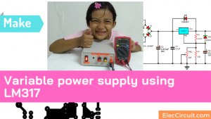
First My Power Supply
I built It as the first power supply. Though it is very old, we have still used them for more than 20 years. Why it is great like this?
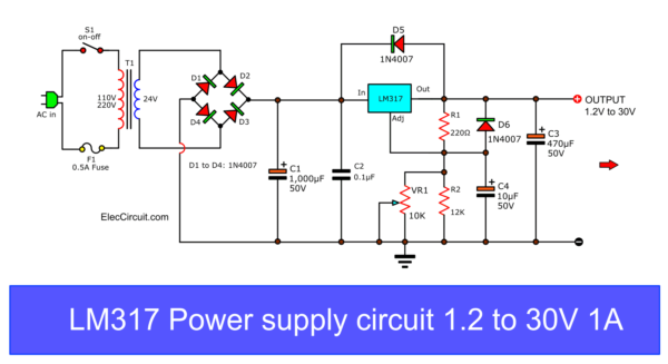
Create: LM317 Power supply
Linear Selector Power supply Regulator
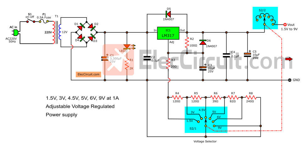
Easy to select the ouput voltage regulator: 1.5V, 3V, 4.5V, 5V, 6V, 9V at 1.5A
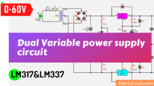
30V Dual DC variable power supply
High voltage 0V to 60 volts at 1.5A and starts voltage at zero! good job.
Great DC power supply
High quality, 3A adjustable voltage regulator. Using LM317 and 2N3055 so easy and cheap. Adjust voltage in steps 3V, 6V, 9V, 12V. And In fine, 1.25V to 20V.
4 Lead Acid Battery charger circuits
See 4 LM317 Lead-acid battery charger circuits for 6V, 12V, and 24V battery. With automatic charging and full charged Indicator using TL431. Easy to build.
Dual power supply 3V,5V,6V,9V,12,15V
Dual power supply circuit,can select voltage levels 3V,5V,6V,9V,12,15V at 1A and -3V,-5V,-6V,-9V,-12V,-15V at 1A, use LM317 (positive) LM337(negative) […]
USB Battery Replacement
This is a USB 5V to 1.5V Step-Down Converter Circuit. When we use a Cheap MP3 Player which uses only one 1.5V AA battery as its power supply.
Gel cell battery charger circuit
It can charge any size of the Gel cell battery and extend the life of the Gel Cell battery. While the circuit is running, the LED indicates charging.
Nicad Battery Charger using LM317T
Here are Universal NiCd and NiMH battery charger circuits. It uses the LM317 Control Current of less than 300mA, Size battery 2.4V,4.8V,9.6V. Low-cost circuit
Related Posts

I love electronics. I have been learning about them through creating simple electronic circuits or small projects. And now I am also having my children do the same. Nevertheless, I hope you found the experiences we shared on this site useful and fulfilling.
Thank’s & GBU this EC member .
sir i want 5v,2a power supply circuit with calculation from 230
pleasr can this idea be used to build solar charge controller?
Pls suggest any simple circuit which supplies output of +12V , -12V dual output with current rating of 1A
I/p supply is +24V DC .
IAM LEANING A LOT I THANK VERY MUCH OUT OF THE MANY THINGS U ARE REVIEWING.
Dear Sir/Ma
We are spare part supplier in Nigeria,
Company name with address
DE- ACCORD SYNERGY CONCEPT NIG LIMiTED. NO6, Oba Amusa Avenue Sumbol Bus Stop, Lagos Nigeria.
Kindly quote us for the bellow items for our customer.
LM78S40 (Universal Switching Regulator) 2nos
LM7805 (Voltage Regulator) 2nos
Your best price and delivery
Best Regards
Abiodun Ogundipe
+23435766398
sir i want a simple voltage regulator for increasing and decreasing the small halogen bulb
input voltage is 12v AC and out put 6v dc with variable pot using matal cap transistor like LM317K.
Hello, Kumerasan
Thanks for visiting.
It is a good idea. Let me give you a comment. What is the small halogen rate, current or watts? Here is 5watts https://amzn.to/2XTskJm
It uses current about 5W/6V = 0.8A. Yes, you can use LM317. It may very heat. But if you use 10W. It will use current more = 10w/6V = 1.6A.
You cannot use alone LM317. You may use it with a power transistor. Or use LM350. It is easy, too. https://www.eleccircuit.com/lm350-adjustable-voltage-regulator/
I hope this can help you.
Ps. I also had the idea of using hydrogen tubes for my chickens.
Do have chickens?
It’s difficult to understand those sentences without grammatic and ortographic sense…
Hello m0n0,
Thanks for your opinion. I will try to improve my English. I hope you will read this article again.
Thanks a lot again my friends.
not seen someone commented this values:)
11.83V : R1 = 390Ω, R2 = 3.3K
12.40V : R1 = 390Ω, R2 = 3.3K
Elkido.
I want to make a power adapter Charger 100-240v input
19-volt dc output. Can i use the typical circuit diagram above?
please forward to me the required component and the circuit diagram to build this project.
I understand that you will use an AC adapter as a 12V battery charger. It can do it. We can use the circuit to reduce the voltage from 19V to 13.5V. Because If we charge the battery with 19V. It will be overcharging, with a high current.
My daughter made this circuit it works very well.
https://www.eleccircuit.com/gel-cell-battery-charger-circuit/
It is cheap and easy with LM317 We use it for 12V 3A to 7A battery.
If it is a higher battery we need to use a long time charging or change the circuit to a higher current.
God bless you.