Morning sun alarm circuit using IC-4011
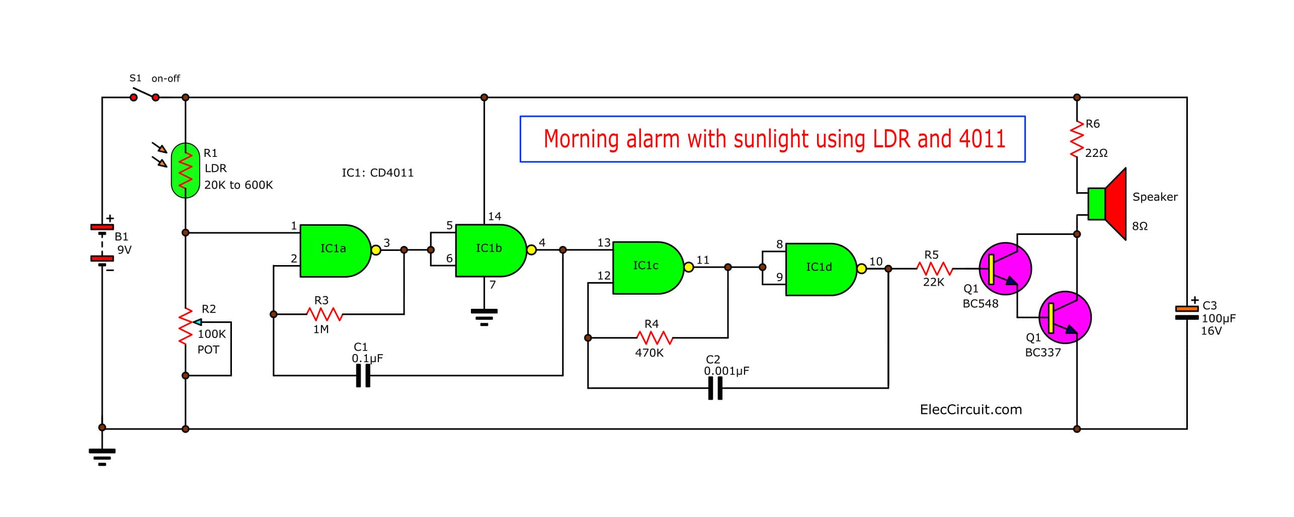
This is Morning sun alarm circuit using IC-4011 that hobby It will have sound alarm when morning like a normal clock alarm with lighting sensor same clock. Read more
This is Morning sun alarm circuit using IC-4011 that hobby It will have sound alarm when morning like a normal clock alarm with lighting sensor same clock. Read more
This is Simple Solar light alarm circuit with the special edition, that improve this circuit whole new to higher efficiency. use solar cell instead of LDR Read more
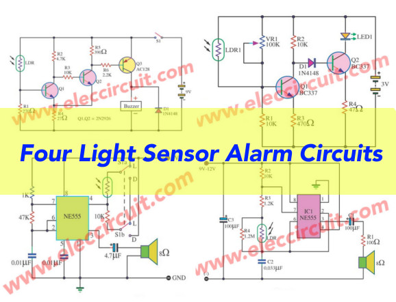
These are four light sensor alarm circuits, when be become dark, or Light sensitive switch.Use part is important light sensor LDR light dependent resistor […] Read more
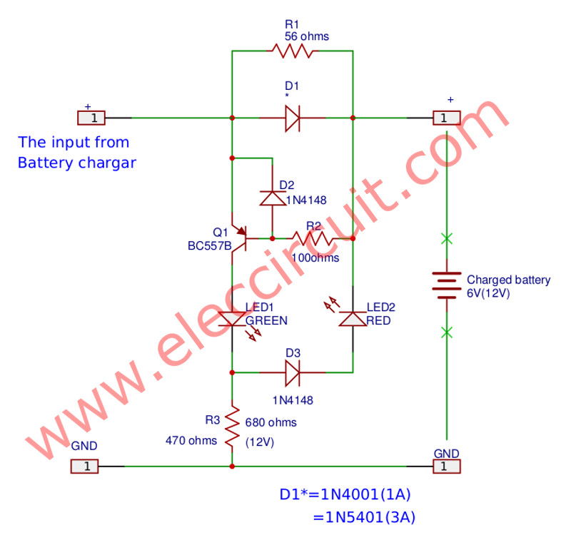
The Battery full charge alarm circuit for a general battery charger. It is simplified circuit and cheap, use one transistor BC557 and display with 2 LED. Read more