Low Voltage Battery Indicator circuit using LM339
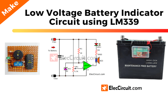
The simple low voltage tester circuit using LM339,can use Battery voltage monitor for voltage sources that problems, by LED display and alarm sound. Read more
The simple low voltage tester circuit using LM339,can use Battery voltage monitor for voltage sources that problems, by LED display and alarm sound. Read more
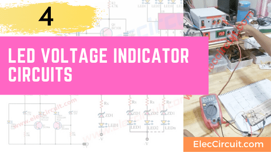
This is four circuits of LED voltage indicator are simple and easy to builds for check voltage battery and others, use as zener,transistor,LM339 and more Read more
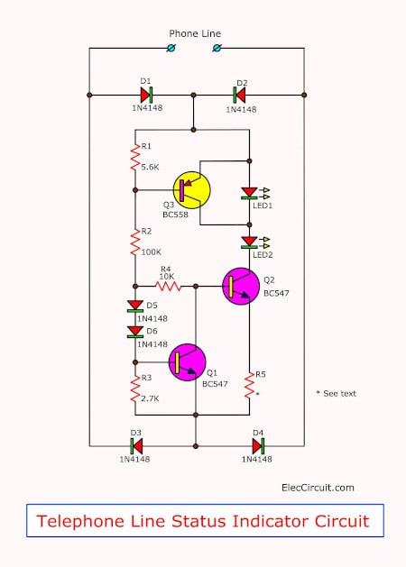
The telephone line status indicator to prevent the hearing others talk on the phone accidentally and a Protection to making phone calls simultaneously. […] Read more
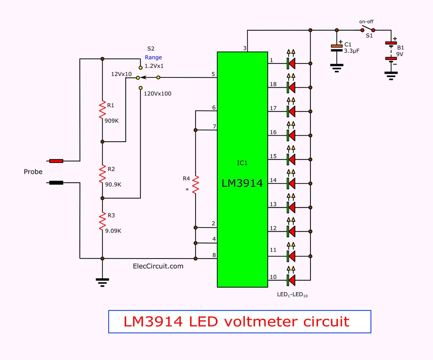
This is Simple LED voltmeter circuit using LM3914, can measure any volts 1.2V to 1200V on 3 range with 10 LED display easy to look and use 9V battery Read more