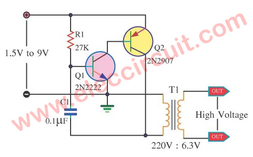
Small High Volts shock using 2SC1815 transistor
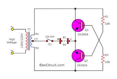
This is small high volts shock circuit, pressure from the low current. It is perfect for fun play. In circuit has a few component just two small NPN transistors, 2 resistors and a transformer. So easy to builds and cheap! Do not wait..lets build it. Read more