Automatic Fan Controller circuit
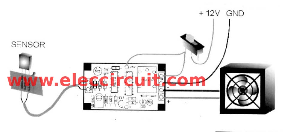
This is automatically fan controller for heatsink. when it hot so the fan controlled to high speed. it use LM334z as temperature sensor that is accurate. […] Read more
This is automatically fan controller for heatsink. when it hot so the fan controlled to high speed. it use LM334z as temperature sensor that is accurate. […] Read more
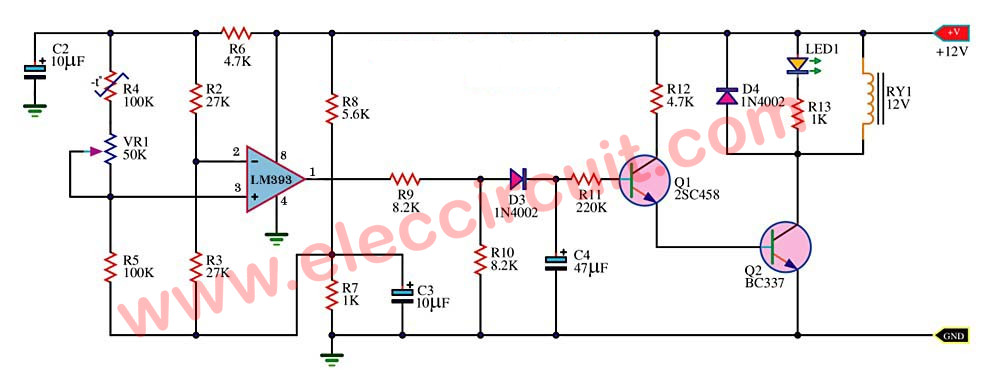
The temperature controlled on off relay circuit,main ideals is thermistor will change its resistance.IC1-LM393 to bias transistor to drive relay works. […] Read more