How Astable Multivibrator using Logic Gates work | Example Circuits
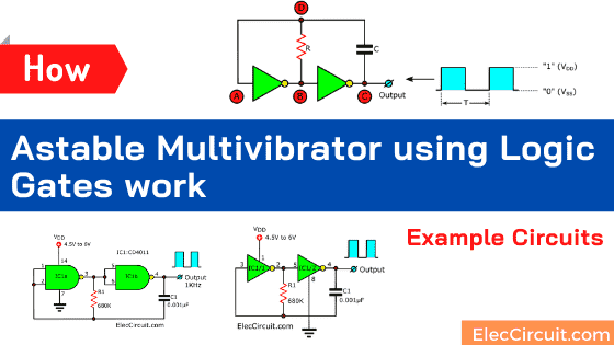
Learn how astable multivibrator using logic gates works in simple diagram. With example 5 oscillator circuits, NAND, NOR, Inverter, Not gates etcs Read more
Learn how astable multivibrator using logic gates works in simple diagram. With example 5 oscillator circuits, NAND, NOR, Inverter, Not gates etcs Read more
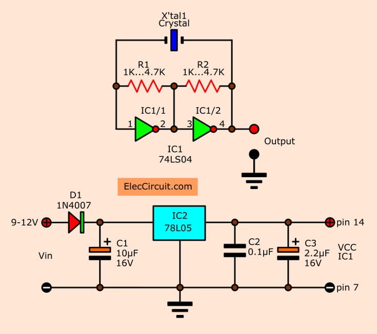
This Simple Crystal oscillator Circuit using 74LS04 that provided square wave of 1MHz to 10MHz, Use inverter gate IC and control frequencies with crystal […] Read more

The Monostable Multivibrator circuit additional a circuits taht is very useful is One-Shots circuit or Also known as Mono-stable multivibrator circuit. Read more