CD4017 datasheet & Pinout and working explained
IC 4017 CMOS-Decade counter/divider. When we build the 10 LEDs running light for hobby. Often use IC-4017. This really neat chip contains counter,decoder[…] Read more
IC 4017 CMOS-Decade counter/divider. When we build the 10 LEDs running light for hobby. Often use IC-4017. This really neat chip contains counter,decoder[…] Read more
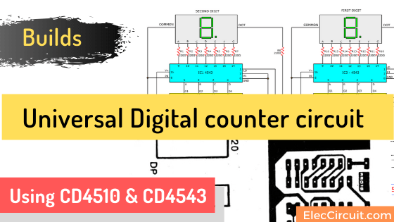
This is Universal digital counter circuit using CD4510 & CD4543,count up or count down,connect output to a 7 segment LED both a Cathode common or Anode Read more
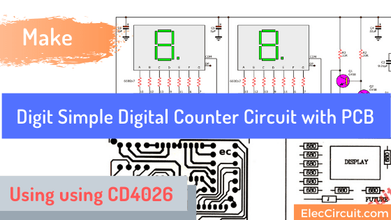
This is 2 Digit Simple digital counter circuit using CD4026 as main parts can display with LED 7 segment 0-99 number There is a reset button to restart. Read more
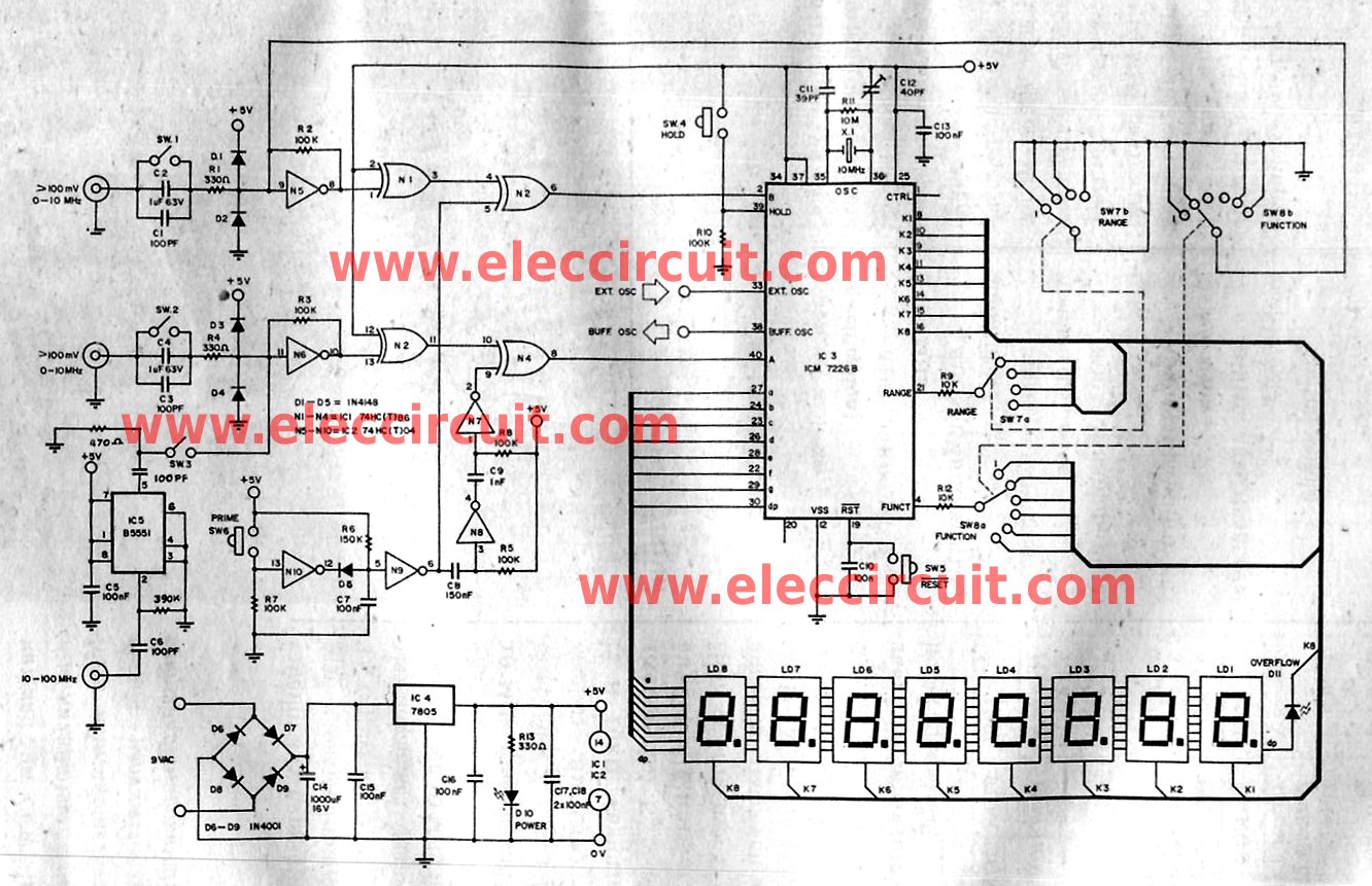
The Multi function digital frequency meter circuit 0-100MHz, is an instrument that can measurement many things in a single display with LED 7 segment 8 digit. The controls measures sector as well as the display is used a single master IC. Is A good IC of Intersil Corporation. ICM 7226B is a single IC at … Read more
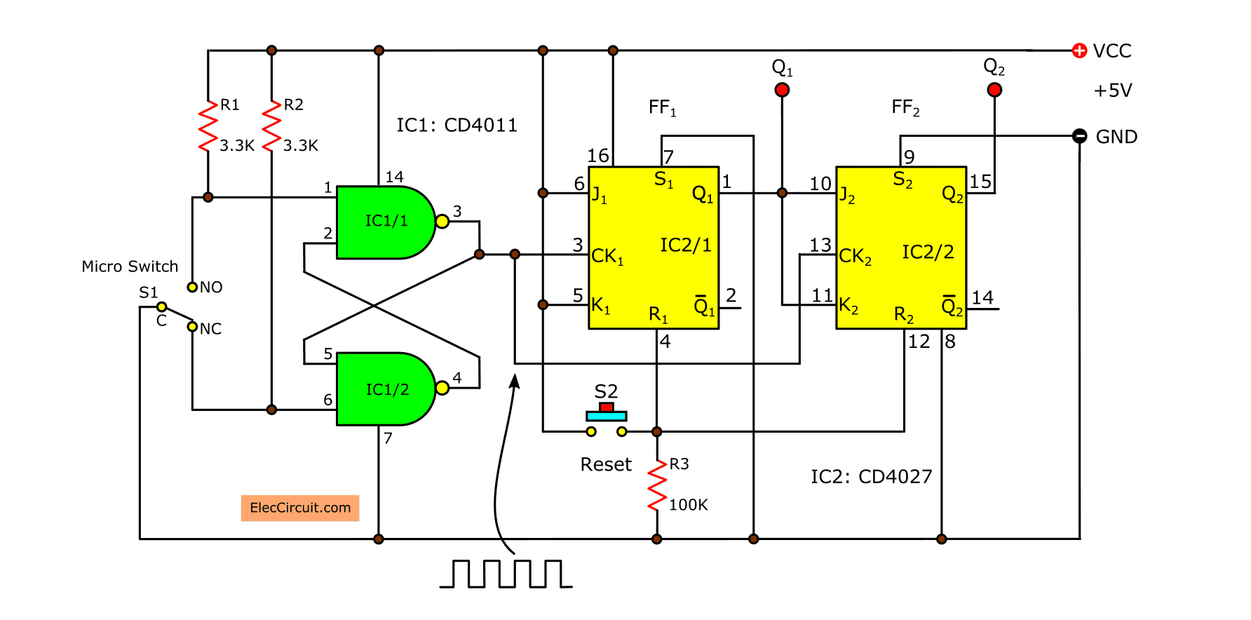
We are experimental to create a simple counter circuit today, is a 2-bit binary counters.Which consists of the gate and flip-flop both of TTL-IC type. We use the ICs are NAND Gate number: SN7400N and the flip-flop No: SN7473N, which consists of JK-FF two pieces. We use only one at a time, so can try … Read more