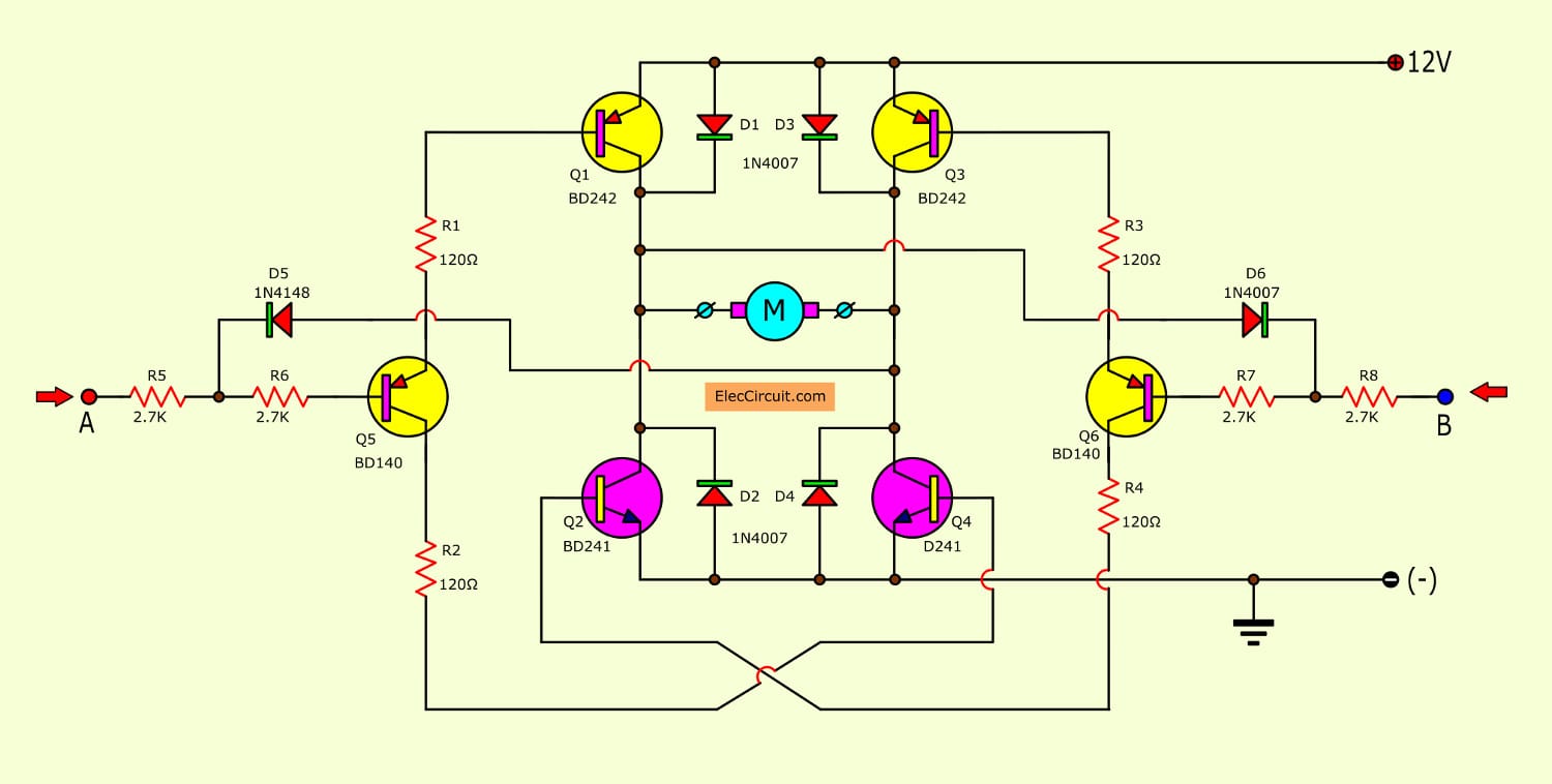
Basic H-bridge motor driver circuit using bipolar transistor
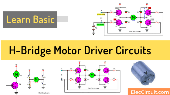
It is a H-Bridge motor driver circuit that popular, high performance,to moving of a robot,designed by mosfet or transistor to control rotating of motor[…] Read more
It is a H-Bridge motor driver circuit that popular, high performance,to moving of a robot,designed by mosfet or transistor to control rotating of motor[…] Read more
It is easy if you control DC motor in a single direction. Sometimes you think. How to rotate DC motor in both directions. You are not worried. There are many ways to control speed, on-off, and dc motor reverses rotation. Read first: How does H-bridge motor driver works In these circuits below use many types … Read more