5-minutes Power Off Delay Timer Circuit
Want to have longer lighting with the original battery? Let’s learn the concept and design of the power off delay timer circuit in a simple way. You may apply it indefinitely. Read more
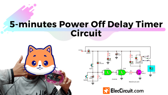
We can use CD4093 to build many circuits. See below.
Want to have longer lighting with the original battery? Let’s learn the concept and design of the power off delay timer circuit in a simple way. You may apply it indefinitely. Read more