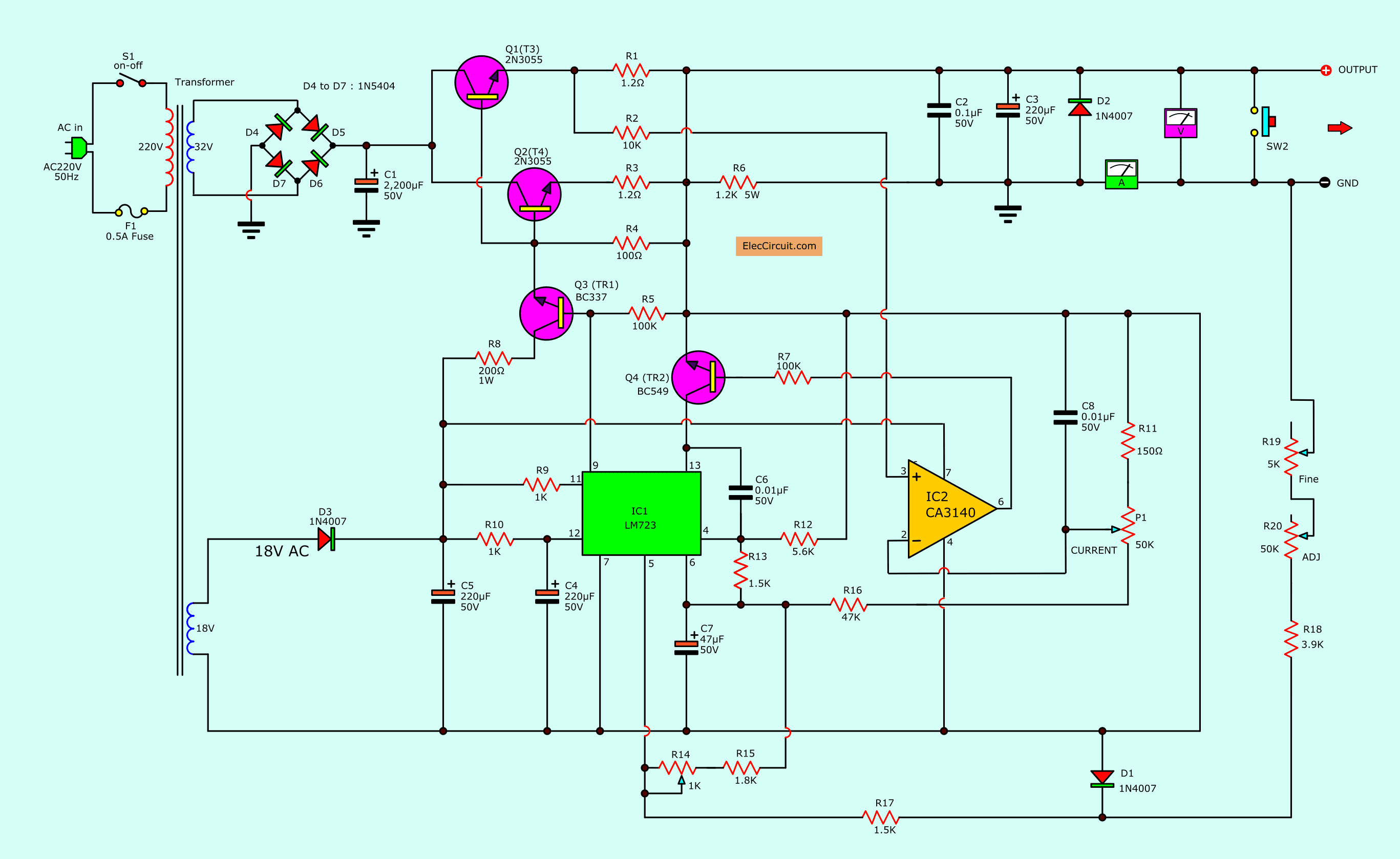
0-30V 0-5A regulated variable power supply circuit
Do Not Make This circuit If You are not brave enough. Read more
Do Not Make This circuit If You are not brave enough. Read more
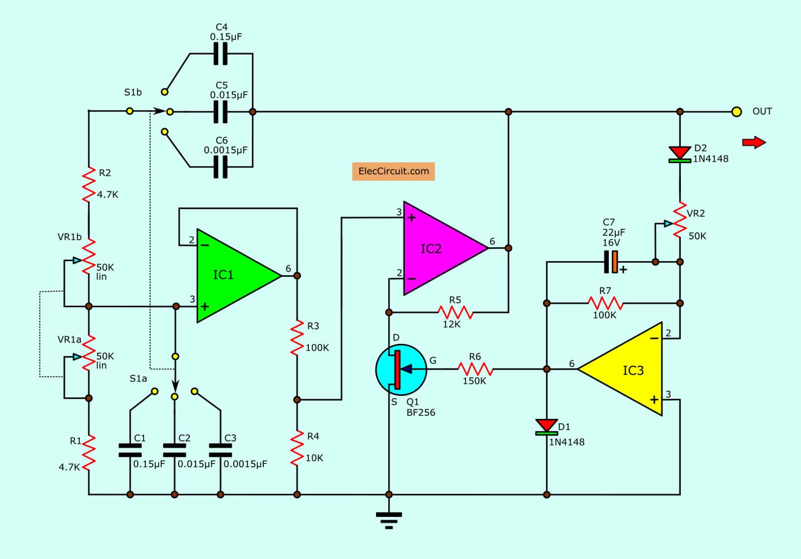
This is sine wave bridge oscillator circuit more: Read more
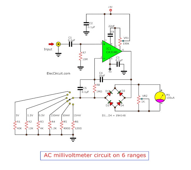
Sometimes, we need to measure a too tiny AC voltage level. And high frequency too. Ohh… We cannot use general multimeter. I recommend you try watching the AC millivoltmeter circuit. It includes the 6 ranges. Lowest is 15mV only. Also, it uses an analog meter form. So, you can watch easily a slow changing of … Read more
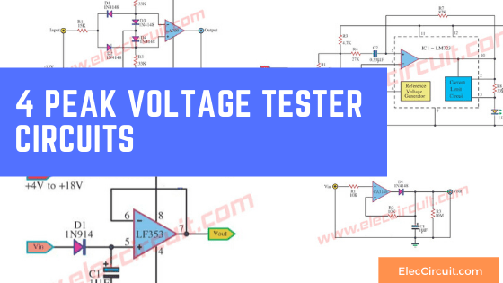
If you want to check the peak voltage of the signal to change at any time. Measuring with a multimeter will not do it. We recommend this circuit. It may help you. Precision Peak voltage detector with a long memory time We use this circuit The op-amp IC number CA3140 is the main equipment, acts … Read more