Video amplifier splitter using transistor

The video amplifier splitter circuit, it is designed to take video signal is stronger. Compensate for the loss of signal, and is video splitter video […] Read more
The video amplifier splitter circuit, it is designed to take video signal is stronger. Compensate for the loss of signal, and is video splitter video […] Read more
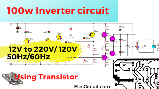
This is inverter 12V to 220V that 100W output using all BC557 PNP and 2N3055 transistors so easy to build and cheaper, we use 12V 10Ah and transformer 5A up. […] Read more