I am going to show you an AC dimmer circuit for LED bulbs. Now the LED bulbs are higher quality and cheaper.
Same as normal incandescent bulbs. If it is dimmable LED we can adjust its light.
In this circuit, there is special than other circuits. But I believe It has high efficiency. Because use IC-555 and TRIAC.
DO you try to prove it?
Recommended: Dimmer circuit using SCR – TRIAC
The working principle
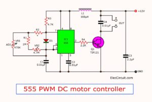
Look at the circuit diagram below.
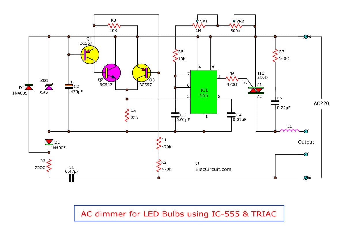
To begin with, the capacitors C1 and R3 reduce a level AC voltage to both diodes D1 and D2. To rectifier as DC voltage.Then, both zener diode ZD1 and C2 will maintain the regulated voltage.
Next, this voltage is power for IC1,555 timer. It is set as the monostable multivibrator.
Which it have Q1 through Q3 generate a pulse to trigger (pin 2) of IC1. The time period output of IC1 can adjust with VR1 and VR2
Recommended: How does NE555 timer circuit works
What is more?
See in the graph below.
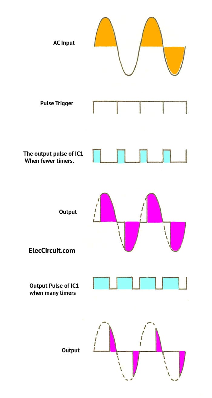
When trig a pulse is “0”. The C3 will start to charge pass through R5, VR1 and VR2. While C3 is charging. At output of IC1 will have level is “high” or the same level as the A1.
It makes the TRIAC does not conduct current. When C3 charge until fully. The output of IC1 will drop as “Low”.
So, causes the TRIAC conducts current. It depending on the time constant of C3, C5, VR1 and VR2.
If the time constant is too much. It causes the time that TRIAC conduct current is fewer.
In contrast, the time constant is lower. The time period conducting of triac is many.
Which depends on the VR1 and VR2 there. They L1, R7 and C5 are the high frequencies filter circuits because switching of TRIAC.
Read Also:555 PWM LED dimmer circuit diagram
When we use the TRIAC:TIC-206. So can be used within 600 watts. If you use more than this. Need to change the another number. Resistant want that currents.
For L1 coil we may made by the AM radio ferrite rod. Cut to about 5 cm. Then, use enameled copper wire # 20 wrap fully around the core. Next coated with varnish.
Recommended: SCR circuit diagram
Customization
- First of all, connected load is lamp to the output.
- Second, enter AC line 220V to the circuit.
- Third, adjust VR2 clockwise to the end.
- Fourth, then adjust VR1 to the LED go out.
- Fifth, Try to gradually adjust VR2 clockwise, to observe the gradual illumination lamp.
- Then, it is best brightness, adjusting VR2 completely.
- Next, if abnormal, repeat from the beginning, but the VR1 on the other hand.
This project can use for only Dimmable LED Light Bulbs.
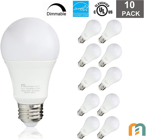
Look at photo:
The parts list
Resistors 0.25 watts
R1, R2: 470K
R3: 220K, 0.5 watts
R4: 22K
R5: 10K
R6: 470 ohm
R7: 100 ohms, 0.5 watts
Potentiometer
VR1: 1M
VR2: 500K (B)
Capacitors
C1: 0.47uF 630V mylar.
C2: 470uF 16V electrolytic.
C3, C4: 0.01uF 50V mylar.
C5: 0.022uF 630V mylar.
The semiconductor
IC1: NE555
TR1,TR3: BC557B
TR2: BC547B
D1,D2: 1N4005
ZD1: Zener diode 5.6 volts 0.5 watts
Triac: TIC-206D
Photo Credit: LED Light Bulbs 10 Watt by Mastery Mart
Caution
While tuning. Do not touch any part of the PCB. Or heat sink may be a danger of electric shock.
Here are a few related posts you might want to read:
- 3000 watts Dimmer for Inductive Load
- How to changing dimmer to normal switch
- Music dancing light circuit,4500 watt using opto isolator

Related Posts


I love electronics. I have been learning about them through creating simple electronic circuits or small projects. And now I am also having my children do the same. Nevertheless, I hope you found the experiences we shared on this site useful and fulfilling.
I really like your website, but unfortunately I find most of your descriptions to be very, very difficult to understand. English is not a language you are very fluent in. Actually, if you saw this in your own native language you’d get a good laugh. Perhaps if you posted in both english and a language you are very fluent in, more people could understand.
Thank-you for your website. I do not wish to complain! Any improvements will be appreciated.
Amazing stuff. Thank a lot for posting this. I’ll check to your site to find out more and recommend my friends about this.
Hi, Gary Dering
Thank for your comment.
Although I have very poor English.
I will post again, hoping that everyone will benefit. Little. I’m glad it.
I can understand and expect your english not to be 100% But I have no trouble understanding what you mean. After reading some of the chinese leaflets translated to english then that’s when you have trouble. Over in england we call it chinglish
Hi Paul Brace,
First, I feel good to read your text. Thank you.
It is true. My English is not good. I will try to improve my English.
You are kind. Can you help me develop it grow up?
Thanks again my friend.
Hello,
I want to make this circuit to controle an motor over 400 W.
It’s possible with this circuit ?
I wait for your response.
Best,
Vasile
I wld like
I have often thought that if you pwm’d a triac it would work but didn’t know if a triac would be fast enough
So good en teaching for electronics beginners like mi I have just got to realize the site today. I will keep on following u . Post more, thanks