Use NE556 better. Why? Imagine you use often the 555 timer circuit. It is so great, right? Of course, we should improve our circuit. Small and save money.
NE556 is a dual timer of 555. It is two in one. So, save space and cheaper.
In this article, we will learn how does use it, datasheet. See pinout, block diagram. And Look at the example circuits. You may apply them to do great your working.
Recommended: How does NE555 timer circuit works
NE556 Datasheet
The LM556 Dual timing circuit is a highly stable controller. And, they can produce accurate time delays or oscillation.
The NE556 will contain 2 NE555. The timing is provided by an external resistor and capacitor for each timing function.
The two timers section operate independently of each other. It shares only VCC and ground.
The circuits may be triggered and reset on falling waveforms. The output power of 200mA max.
Features
- Direct replacement for LM556/SE556
- Timing from microseconds through hours
- Operates in both astable and monostable modes
- Replaces two 555 timers
- Adjustable duty cycle
- Output can source or sink 200mA
- Output and supply TTL compatible
- Temperature stability better than 0.005% per ˚C
- Normally on and normally off the output
Applications
- Precision timing
- Pulse generation
- Sequential timing
- Time delay generation
- Pulse width modulation
- Pulse position modulation
- Linear ramp generator
Using NE556
We should use the NE556 on this detail:
- VCC—the supply voltage: 4.5V to 16V
- Vi—the input voltages(all): VCC
- Io—the output current: 200mA
- TA—Operating free-air temperature: 0 – 70C
Pinout connection
How to use NE556. First of all, need to know the pinout of NE556. Look at below. It is a 14-DIP packet that looks like a CD4011 NAND gate or LM324 op-amp.
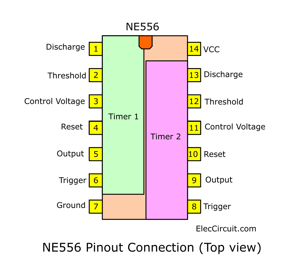
We can compare the pin connections of NE555 and NE556
| Function | NE555 | NE556 (Timer1) | NE556 (Timer1) |
| Ground | 1 | 7 | 7 |
| Trigger | 2 | 6 | 8 |
| Output | 3 | 5 | 9 |
| Reset | 4 | 4 | 10 |
| Control Voltage | 5 | 3 | 11 |
| Threshold | 6 | 2 | 12 |
| Discharge | 7 | 1 | 13 |
| Vcc | 8 | 14 | 14 |
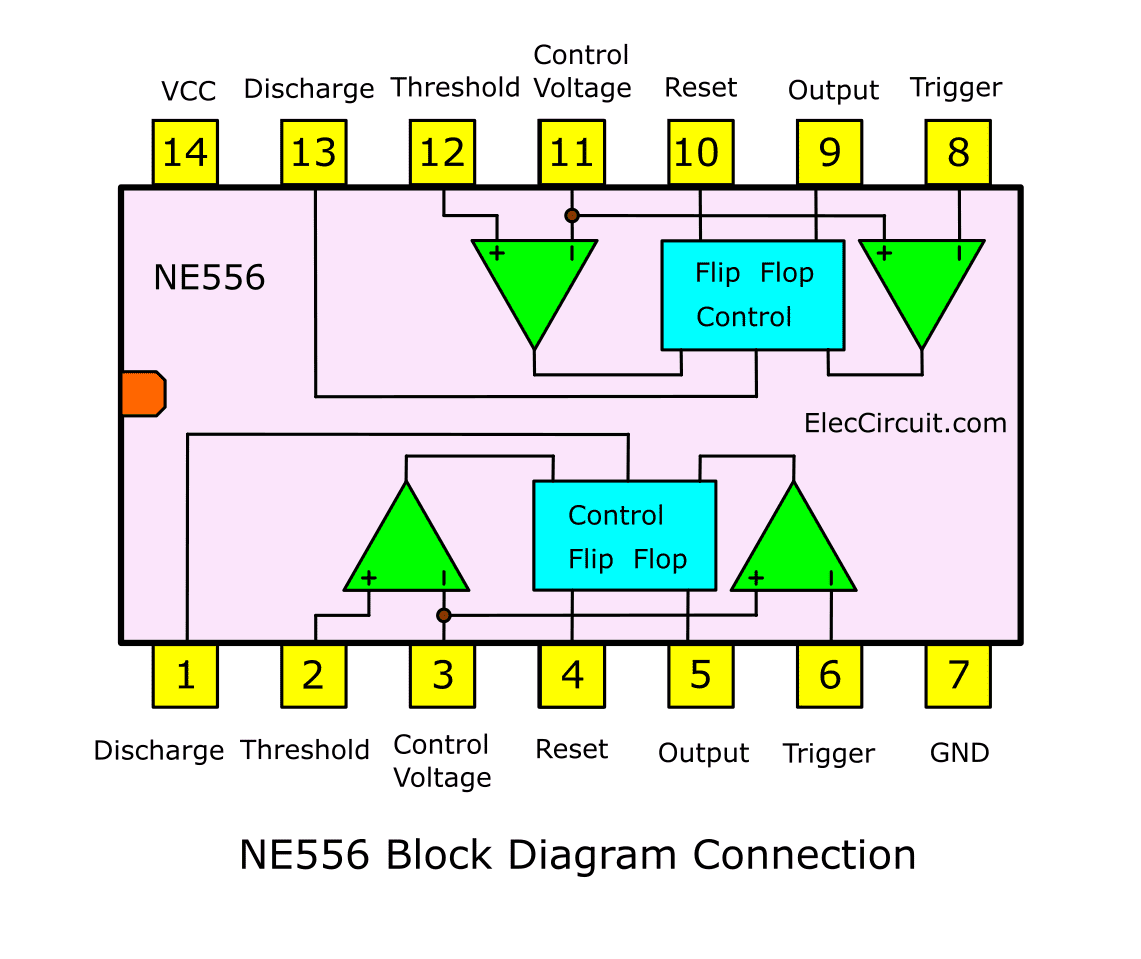
Block Schematic Diagram
In NE556 there are many electronic components assembled into circuits, as shown.
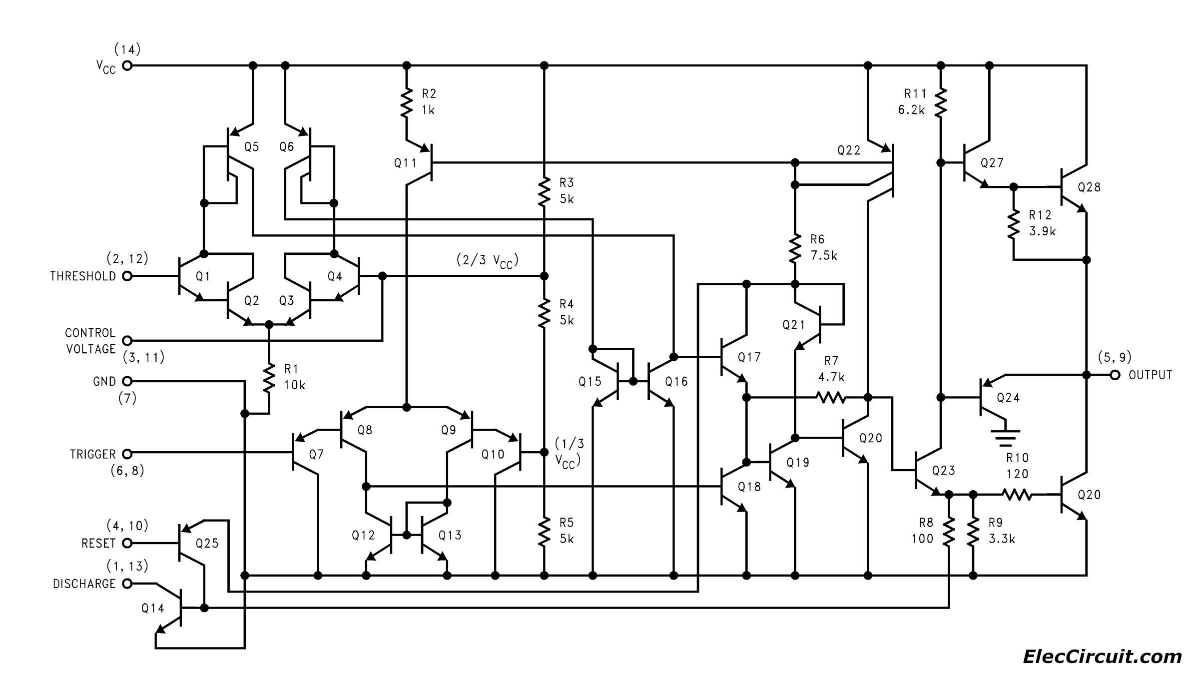
But it is difficult To understand its operation. Let’s look at a block diagram better.
Example Circuits of NE556
Good learning is often from actual use circuits. See many examples of circuits. It may make your understanding more.
Simple Train Whistle circuit using NE556
This is a simple train whistle circuit. We have many ways to generate a two-tone sound circuit. I love to collect a basic or small circuit.
This circuit may be useful for you. When we press SW1, the speaker will emit the sound like a train whistle. It is suitable for sound alarms and others.
The main component of this circuit is NE556, a great integrated circuit.
This advantage of this circuit is small and cheap. Because it uses a single IC. Working out sound speakers directly.
How this circuit works
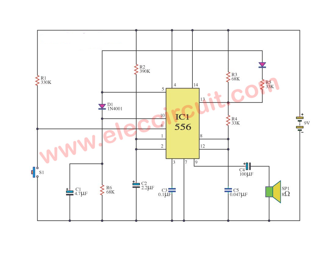
Simple train whistle circuit diagram
When we take the 9v power supply(9V battery) to the circuit. It will start to generate low frequency out of pin 5. A separate section to the pin 9 to the speaker driver. This Frequency depends on the R2 and C2.
The signal from pin 5 comes to pin 8. And there is R6 and C1 to reset with a delay circuit.
When it is reset, pin 8 gets the signal and this circuit will generate a high-frequency signal that comes out of pin 9 of IC1. Which there is R3, R4, C5 to set this signal.
Thus, the characteristic of the sound is to start the high-frequency sound. Then change to low frequency.
Parts you will need
IC1: NE556 Dual Precision Timer
D1,D2: 1N4001 1A, 50V Diodes
Ceramic capacitors
C3: 0.1uF 50V
C5: 0.047uF 50V
Electrolytic capacitors
C1: 4.7uF 50V
C2: 2.2uF 50V; Quantity:1
C4: 220uF 16V; Quantity:1
0.25W Resistors, tolerance: 5%
R1: 330K
R2: 390K
R3, R6: 68K
R4, R5: 33K
B1: 9V battery
SP1: 8 ohms speaker
Electronic organ circuit
This is a Mini Organ circuit using N556. Now maybe the era of microcontrollers and computers. But having a basic level of electronic capabilities is still necessary. I like to collect electronic circuits. For everyone’s learning.
See in the circuit below. I am going to show a simple NE556 circuit with mini-organ.
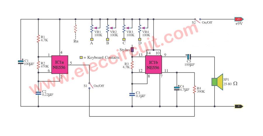
When you will think to build Single IC Organ Circuit the some one. I begs for to advise this circuit , because use IC NE556 or LM556. Which within its structure is like have the integrated circuit IC 555 arrive at 2 together follow my circuit. Control by Keyboard contacts and SW1 Tremolo ON/OFF as a result can choose music pitch that can want.The detail about mini Organ Circuit the this. Can see in circuit.
Insects and Mice repellent circuit using IC556
It uses a high frequency out of the piezo speaker. And IC-556 is base as oscillator between 22kHz and 56kHz.

This project is interesting to build with PCB layout. If you have a problem with rats And pests try this circuit, it is a good solution.
It is very detailed. If I add this content. Of course, this article will be too long. So if you are interested in it. Please read more here.

Related Posts


I love electronics. I have been learning about them through creating simple electronic circuits or small projects. And now I am also having my children do the same. Nevertheless, I hope you found the experiences we shared on this site useful and fulfilling.
i like this circuit
Hi, aamir sohail
Thanks.
I appreciate your electronic site and your experience too,please show me how I test a power triac and power transistor and a darlington