This is a simple ic 4011 led flasher circuit that I would link to suggest you make it. But before you can use transistors.
Which is difficult when we learn about digital ICs. In particular, IC 4011, has been very popular.
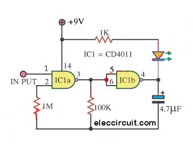
From this circuit: Easy ic 4011 led flasher circuit I apply to new stye display with a Single LED, by I use cool digital IC, GATE Flasher IC-4011 quad NAND gate.
So the Flashing output frequency = 1Hz. The IC 4011 ‘s Input pin 1 use for Control LED ON or Flasher.
Logic = Low (LED ON) , Logic Hi = LED Flasher. I like this circuit because it is easy to make.
Detail more, Please read in this image circuit. and you can see the next circuit of Two LED Flasher
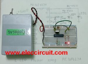
Here is Breadboard layout
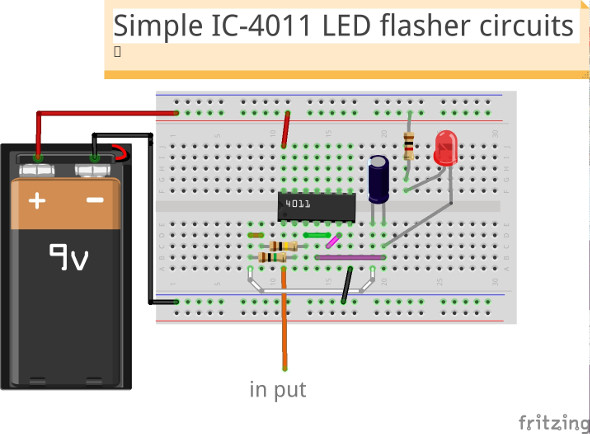
As the video below you can see this circuit that I test on a breadboard. It’s workes!
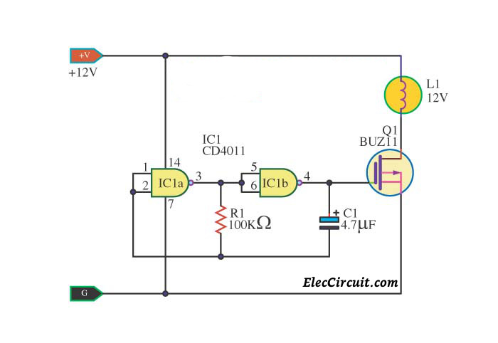
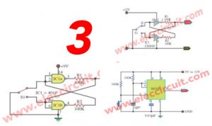
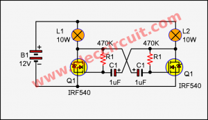
This is Easy Lamp Flasher Simple lamp flasher, I uses NAND Gates IC 4011.
The circuit is an astable multivibrator generating at 50% duty-cycle square wave about 1Hz.
The C1 – 47uF capacitors and R1 – resistors determine the flasher rate frequency.
You must use a High current power supply for the lamp only.
I use power MOSFET for driver lamp because it has high power and easy than a transistor.
please see part of the circuit in the image.
Related circuit: 1.5V LED flasher circuit using transistor, output 5 LEDs with only one AA battery.
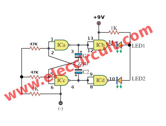
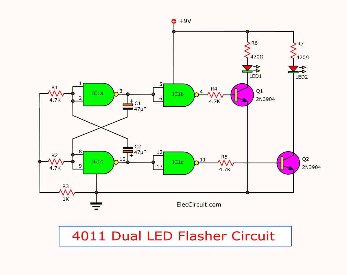
Two LED Flasher using Gate of IC-4011
IF you want the small circuit two LED Flasher, I show this circuit.
The important part of the circuit is IC 4011 again, I used the gate of IC 4011 (see image).
IC wired as an astable multivibrator generating a 50% duty-cycle square wave at about 1Hz frequency.
Two LEDs are flasher to alternate.
To change value C1 and C2 for another flasher ratio.
Detail more, Please read in this image circuit.
See video to test this circuit on breadboard.
From the circuit below it lower light LED I think this circuit better.
This simple circuit uses NAND Gates to alternately flash two LEDs. The two 47uF capacitors determine the flash frequency.
It is a good idea to use a decoupling capacitor across the power supply.
I made this circuit using the components shown and it worked fine.
The IC that I used is the 4011 Quad
2-input NAND Gate.
As the video below we use LED super bright RED color:
Here are a few related posts you might want to read:
Related Posts

I love electronics. I have been learning about them through creating simple electronic circuits or small projects. And now I am also having my children do the same. Nevertheless, I hope you found the experiences we shared on this site useful and fulfilling.
I need to learn how to make an “engine timing light”, but i didn’t found it in this electronic Project circuit. I’m sure it just a simple circuit and need only one or two electronics component, who has experience this, please send a diagram to share…
Hi,Rosslie Mohd Sake
I so happy for your comment.
You are interested mysite. I am not best electronic circuit,just only who love it only.
I don’t understand about “engine timing light”
Does they are used in car or motorbike?
And around timer , light.
https://www.eleccircuit.com/timer-set-for-30-minutes/
https://www.eleccircuit.com/modified-the-brake-light-into-flash/
If them not good for you please wait me, I will look at them for you in feature.