Here is the inverter working principle. The inverter is a kind of oscillator. It can produce a high-power AC output from a DC supply.
Can we make it? Is it difficult? Is it expensive? Too many Question! This is beginning for learning how the inverter works. I think in the feature it will have more performance in a small size. But basic still is important.
Usually, DC supply is a 12V battery. The inverter will change it into AC 220V, 50Hz to use any appliances.
A battery is the best!
The inverter does make an energy. But the battery is energy or source. I have noticed as follows.
The energy out of the battery is always approximately equal to using the energy of load.
For example, the load requires 10W at 220V AC. So, the battery needs to give the power about 10W at 12V. Also, the battery can give the current.
According to Ohm’s Law. We can find the current of battery should has, is P/V = I or 10W / 12V = 0.8A.
While inverter is working. It will always lose energy inside it. The battery should have the power more than 1A.
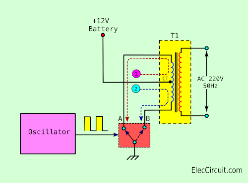
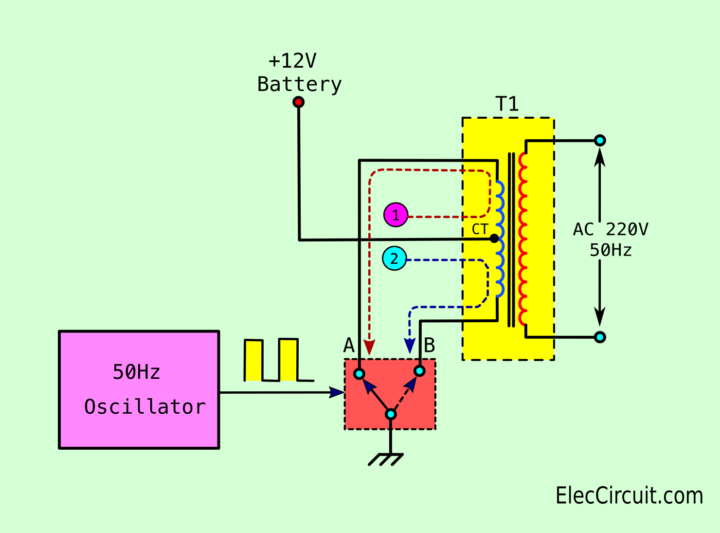
The inverter has a simple working principle as Figure 1.
Which first important thing is the transformer.
The most common type of transformer is the laminated core, 12V-CT-12V.
Normally, the 220V winding is primary. Then, 12V is secondary, the output is 12V.
But this turns. the 12V winding is input or primary. The output or secondary is 220V winding instead.
5 inverter circuits with simple principle
We use this principle to make a lot of circuits. For example 5 circuits lists.
Let’s see their working.
The 12V from the positive terminal of the battery comes to the center tap(CT) of 12V winding. Now it is the primary coil.
The two ends of the coil (A and B point) are connected to the 2 ways switch to the ground.
First, if the switch connects to A point. The current number 1 flows from the battery into CT through A contact of the switch to the ground.
Second, if you turn the switch from A into B. It causes the current number 1 to stops flowing. Then, the current 2 flows to the ground through CT and contact B of the switch.
Third, this 2 ways switch is controlled with the square wave oscillator. which It generates a frequency of approximately 50 Hz.
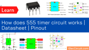
Learn: How to use 555 timer circuits
It causes the switch to selects between A and B point with speed about 50 times per second. Also, the current 1 and 2 flow to the transformer alternately at a rate of 50 times per second.
Now, the current flows into the transformer alternately look like AC voltage.
According to the theory of transformers.The electromagnetic field swells and collapses. And then, a current will be inducted into the secondary, 220V winding.
Which it causes AC voltage 220V 50Hz. The voltage is ready to be supplied to the various types of electrical equipment that require AC 220 Volt in operation.
Choosing transformer in inverter
As above in Ohm’s Law, the transformer can increase the voltage step-up. But the output current always decreased to lower levels.
If you want to take the inverter to 10W load. The current of transformer should be at least of about 1A.‘
Keep reading: Operation of 200-watt inverter diagram
Related Posts

I love electronics. I have been learning about them through creating simple electronic circuits or small projects. And now I am also having my children do the same. Nevertheless, I hope you found the experiences we shared on this site useful and fulfilling.
iwould like u to send me a detaaaaailed information on how tomake an amplifier usind ic no.la 4440
How can i step down a dc 12 volts to dc 3.7 volts thx
HELP
Aap kaise bna sakte h aap ko samjhana h
your explanation is fantastic . all thing is clearly explained hopping you will keep it further
thank you very much
ur explanation is too amazing and thanks for solve my confusion about mechanism of inverter
Very help full information regarding Inverters & their working.
Thanks
Kuldeep Dhar
Thank you for well explation about inverter
I have a school project. I need to design at least a 100w inverter from scratch to finish. how do i go about its design? i honestly need some help here.
Very helpful and simplified information.
Thanks so much.
nice
great work
Very nice explaination .plz gives this project application .where it used
i have a project.I needs to design IC555 INVERTER circuit using MOSFET
GOOD ARTICLE