As usual, we can check a SCR with a plain multimeter. But it is not easy. The Simple SCR tester circuit diagram is very useful. We can know the location pin on the gate lead, anode lead and cathode lead. And can also test diode, LED and Triac.
The SCR devices kind, when take to application with DC voltage. When have trigger current at gate lead SCR will conduction all time. There is one way to stop them is, Remove the power supply voltage that feed it go out it will stop conducts current.
How it works.
As Figure 1 is the SCR tester circuit will see that it is few parts include just three resistors , two LEDs only. The working is very easy. When take SCR to input connector (correctly). When press SW1, LED will still glow.
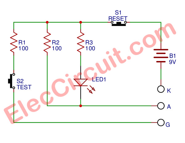
Figure 1 Perfect SCR tester circuit diagram
Then if press SW2, LED will go out all time, indicate that SCR already to uses. But if is tested LED glow. By still not press switch. It indicates this SCR “short”.
The resistors-R1 will limit properly gate current. The resistor-R3 is current limiting to LED about 20 mA and R2 will allow to have current flow in range between 110 mA. The SW1-switch is trigger to SCR stop . Then when press this SW2 , LED1 will go out.
Learn: How SCR circuit works
Building and Application
This project is easy and has a few part. So can solder all components and wire by without PCB.
Application when measure LED or Diode will use just A and K terminal only. If they is good will makes LED1 glow. If backward but still light show that “short”. But id correct polarity LED1 not glow indicate that “blow“
The measuring the SCR testing also use by connecting correct position then press SW1, LED glow. Then press SW2, LED1 should go out indicate that “good” available.
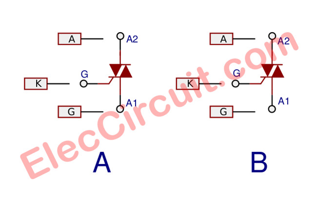
Figure 2 how to test triac.
If insert them but LED1 glow by not press anything to indicate that “short”.
Measuring the Triac can measure them as Figure 2 (A), (B). See in (A) section then press SW1, LED1 will glow. Press SW2, LED1 will go out then measure as Figure (B) again. By press SW1, LED1 will glow. Next press SW2, LED1 will go out as these ways is show that Triac is good.
Since we need to the second measure because the Triac have two ways feature depends on the polarity of voltage between lead gate (G) and lead A1 by A2 is positive. And when lead G is (+) lead A1 will need is (-), when G is (-) lead A1 will is (+) or must not same together.
The component list
Resistors ¼ watts +-5%
R1, R2: 100 ohms
R3: 220 ohms
LED1: LED
SW1: Normally open pushbutton switch.
SW2: Normally closed pushbutton switch.
Others
Copper alligator clips, 9 volts battery with 9v battery snap
Related Posts


I love electronics. I have been learning about them through creating simple electronic circuits or small projects. And now I am also having my children do the same. Nevertheless, I hope you found the experiences we shared on this site useful and fulfilling.