Many people like this circuit It is surprising 1.5V battery can drive LED torch circuit, but some say that the circuit not work.
Today I would like to introduce simple 1.5V LED torch circuit which also uses single AA 1.5V battery. But there are fewer parts. Such as we use one transistor only. And all other parts of 5 pcs only. So easy to build.
The working LED torch circuit
As Figure 1 is circuit diagram, we also the principle of the switching supply.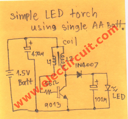
The circuit includes a simple oscillator, a rectifier and dc filter. In the simple oscillator generator, we use transistor-CS9013 and coil L1, L2 as main parts. Which both coils are turned on the same toroidal core like a general transformer.
When we apply the supply voltage to L1 to R1-50 ohms and to bias a base of 9013 transistors, so it conducts current. And then the too much current will flow through L1. It cause have current through the inductor L2 in the reverse direction. Therefore at a collector of CS9013 so have a high frequency fluctuating voltage.
Then it will flow through a diode-1N4007 to rectifier AC to DC voltage and have Capacitors-100uF 16V to filter current to smooth.
Now output has voltage about 4.6V (no load) when we apply LED will drop the voltage to 2.6V can drive to Ultra-bright LED.
Capacitors-470uF 16V at the input is used to add Optimization of battery voltage.
Build winding coil of LED torch
I use this coil inductor : because it is free. Toroidal core used is recycled from defective CFL.
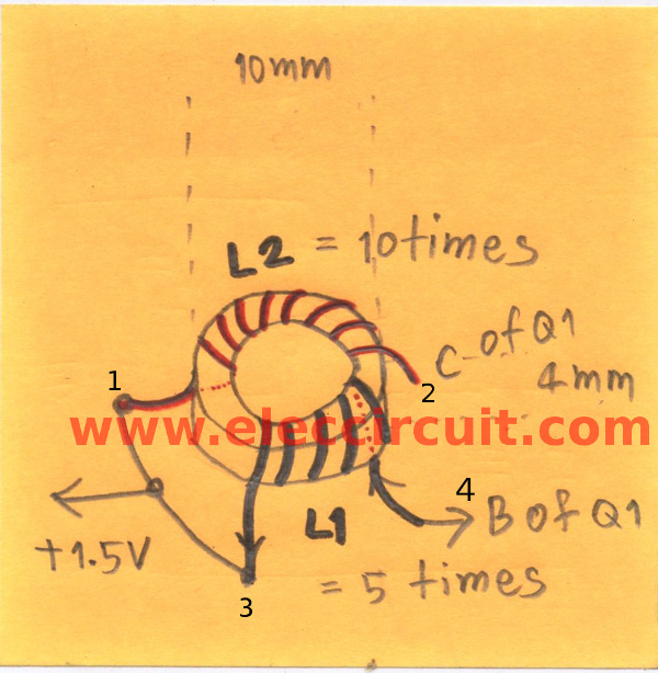
Figure 2
I use copper wires or #30 AWG magnetic wire.
L1 is a feedback winding coil on 5 turns.
L2 is a primary winding coil on 10 turns.
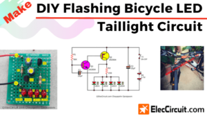
Read also: DIY Flashing Bicycle LED Taillight Circuit
But if no output or the circuit is not working (no oscillation in winding), try to reconnect the winding as follows.
1. Short number 1 and 3 together and connect it to the positive part of the 1.5V supply
2. Number 4 of the winding is connected to 56 ohms resistor.
3. Number 2 of the winding is connected to the collector of the transistor.
This circuit have a few parts so I assemble them on the universal perforated board as Figure 3.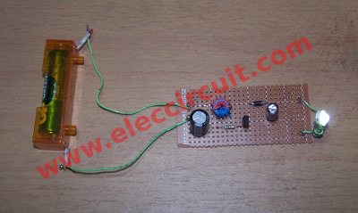
Figure 3. Testing the Simple LED torch using single AA 1.5V Battery
Also : LED torch circuits
Good Feedback from friesays
Dav say to me this is very useful! read below:
Hello Momename,
Nice little joule thief circuit, I very much enjoyed this posting.
I was able to use a much larger toroid and a TIP31 transistor, and it worked just fine.
Surprised me because I usually see a larger voltage supply used with the TIP31.
I had a 50 to 10 turn ratio on my much larger toroid.
The size of the resistor did not appear to matter, as it *also* worked with a 10k ohm for me.
Finally, this delivered 2.5V DC for me, as you state in the article. I noticed that when I removed the smaller capacitor, it delivered about 1.5 VAC.
For me, using the TIP31 transistor, my version did not work with a ‘dead’ battery. I needed to have about 1.2 V battery (or more) to light the LED.
I would imagine just about any low voltage transistor should work with it, such as a 2N3906 or 2222.
I should think that it would also work with a voltage multiplier (using 1N4007 diodes), but what I want to try next is this design with about 300 windings on the toroid (for AC output).
During my first attempt to build this one, it was not clear (to me) exactly how to connect the capacitors on the breadboard. (I had a little confusion regarding your layout of the capacitors.)
I was thinking that for those with problems, maybe a close up of the breadboard might be helpful.
Thank you very much!
– Dave
Related Posts

I love electronics. I have been learning about them through creating simple electronic circuits or small projects. And now I am also having my children do the same. Nevertheless, I hope you found the experiences we shared on this site useful and fulfilling.
I am a electrical engineer .I want to assemble a hand fan with a DC motor which will run on mobile battery .send me the circuit diagram
Dear sir, pls suggest me how to get about 18-20 volt from 6v battery..
Can i use this above circuit to replace 6v
Hi, Abhishek Anand
Thanks for your feedback.
Do you need DC3.8V to 12VDC converter circuit?
How many current of DC motor normally use?
Hi,Prits
Thanks for your feedback.
This circuit cannot use for 6V input. since it simple circuit.
If you need this circuit please try it circuit : https://www.eleccircuit.com/the-many-dc-to-dc-converters-using-ic-555/
or https://www.eleccircuit.com/simple-dc-to-dc-step-up-converter-using-tda2822/
or https://www.eleccircuit.com/category/dc-converter/step-up-dc-converters/
How many current you need?
Hello Momename,
Nice little joule thief circuit, I very much enjoyed this posting.
I was able to use a much larger toroid and a TIP31 transistor, and it worked just fine.
Surprised me because I usually see a larger voltage supply used with the TIP31.
I had a 50 to 10 turn ratio on my much larger toroid.
The size of the resistor did not appear to matter, as it *also* worked with a 10k ohm for me.
Finally, this delivered 2.5V DC for me, as you state in the article. I noticed that when I removed the smaller capacitor, it delivered about 1.5 V AC.
For me, using the TIP31 transistor, my version did not work with a ‘dead’ battery. I needed to have about 1.2 V battery (or more) to light the LED.
I would imagine just about any low voltage transistor should work with it, such as a 2N3906 or 2222.
I should think that it would also work with a voltage multiplier (using 1N4007 diodes), but what I want to try next is this design with about 300 windings on the toroid (for AC output).
During my first attempt to build this one, it was not clear (to me) exactly how to connect the capacitors on the breadboard. (I had a little confusion regarding your lay out of the capacitors.)
I was thinking that for those with problems, maybe a close up of the breadboard might be helpful.
Thank you very much!
– Dave
Hi,Dave.
Thanks a lot for your feedback.
sir i want to make a dcmotor fan please suggested about circuit diagram . it works on mobile battery
Hi,arvind kumar sahu
Yes, you may use this circuit for your DC motor fan.
If it low current use.