I am going to tell you how to use Arduino as a switch. In this, we will learn the simple Button Digital Input using Arduino. It is very easy. Then, apply it with coding to change into a toggle switch on-off.
Are you ready? Let’s get to learn.
Here is a step by step process.
The Arduino has Digital I/O PINs. Which “I/O” is Input and Output. We use the output of Arduino to display the LEDs.
So, we need to use the switches as digital input pins to get various electrical signals to control the operation of the circuit as well.
What is Digital?
Digital is a kind of electrical signal. Which has work of only two states are:
– HIGH or ON or “1”
– LOW or OFF or “0”
We bring this digital Go to the many benefits and high accuracy.
Switch on Arduino (Pull-up, Pull-Down)
What is digital Input?
Digital Pins of Arduino can read 2 status are “HIGH” and “LOW” depend on that Pin has current or not.
The Button switch to Input Pin of Arduino. We need to connect the resistor to exact status of the inputs. We use 2 form circuit
• Pull-Up: the Input will be connected with a resistor that call “Pull-UP Resistor” to a Vin we will have the status “HIGH” all the time, until you press button to LOW or ground, the Arduino will read “LOW” or we call “Active Low”
• Pull-Down: the Input will be connected with a resistor that call “Pull-Down Resistor” to a Ground we will have the status “LOW” all the time, until you press button to Vin or HIGH, the Arduino will read “HIGH” or we call “Active High”
We will see that 2 circuits have the operation reversed. Depending on what is selected.
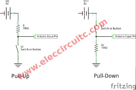
Figure 1 Pull-up and Pull-Down Circuits
This resistor Pull-Up / Down Resistor used the 5K – 20K. We use 10K
Start to build the Button to control LED
We will use the Input Pin of Arduino to receive the button status, then control LED display on Output Pin 13. By using the Pull-Down to apply LED grow up when we press the button only.
STEP 1
Parts will you needs
Arduino UNO R3
- Normally open pushbutton
- one LED
- 10K resistor
- 470 ohms resistor
- jumper wires
- Breadboard
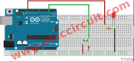
Step 2 connect the parts as circuit Figure 2 The circuit connection
This circuit use Pull-Down by connect the Button to 5V power supply and 10K resistors to ground. And We use Digital PIN 3 as Input. Next, the Output is Digital PIN 13 connected to LED by 470 ? resistor to limit current.
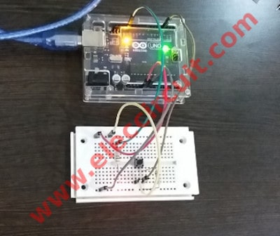
Figure 3 Simple Button Digital Input using Arduino
Let’s test it
We type the code on IDE below
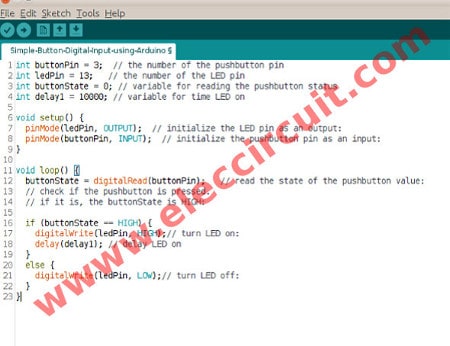
Figure 4 the Simple Button Digital Input code with delay
int buttonPin = 3;  // the number of the pushbutton pin
int ledPin = 13;   // the number of the LED pin
int buttonState = 0; // variable for reading the pushbutton status
int delay1 = 10000;

void setup() {
  pinMode(ledPin, OUTPUT);  // initialize the LED pin as an output:
  pinMode(buttonPin, INPUT);  // initialize the pushbutton pin as an input:
}

void loop() {
  buttonState = digitalRead(buttonPin);   // read the state of the pushbutton value:
  // check if the pushbutton is pressed.
  // if it is, the buttonState is HIGH:

  if (buttonState == HIGH) {
    digitalWrite(ledPin, HIGH);// turn LED on:
     delay(delay1);
  }
  else {
    digitalWrite(ledPin, LOW);// turn LED off:
  }
}
We test it as Video, first type code on IDE without “delay” command. And upload When we press the button LED will glow as we press. Then, we put the code delay. The LED will delay time turn ON about 10S.
Now we use the button or switch as a digital input. It is easy
Learn more Switch – Arduino.
Today we will as push button switch as toggle switch. When we press the button “on” it will store status “on” hold, although, we will release. Then, we press it again it will “off” and store status “off” as well.
How it works and building
We want to control LED ON-OFF by button (as toggle switch). So we use schematic as Figure 1
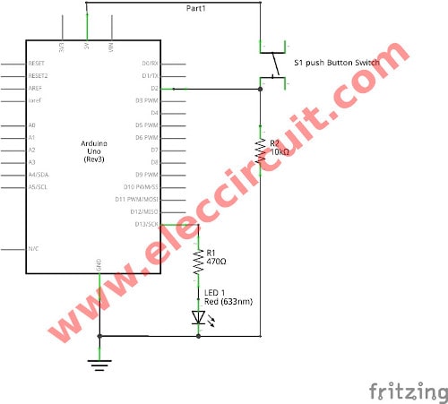
Figure 1 Schematic diagram of The Button becoming Toggle Switch using Arduino
Parts will you needs
- Arduino UNO R3
- Normally open pushbutton
- one LED
- 10K resistor
- 470 ohns resistor
- jumper wires
- Breadboard
Then, we connect parts on breadboard and the arduino as Figure 2
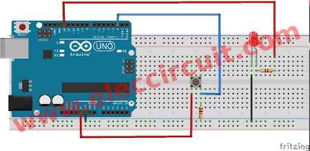
Figure 2 circuits connection on breadboard
We code programming on Sketch – Arduino IDE as code below.
int ledPin = 13;  // the number of the pushbutton pin
int buttonPin = 2;  // the number of the LED pin

boolean buttonState;
boolean lastState;
boolean state = HIGH; // variable for first status

 void setup() {
  pinMode (buttonPin,INPUT);  // initialize the pushbutton pin as an input:
  pinMode (ledPin,OUTPUT);  // initialize the LED pin as an output:
}

void loop() {
  reading = digitalRead(buttonPin);

  if ( reading == LOW && lastState == HIGH ) {
    delay (10);  // To solve the The problem switch bounce
    if (digitalRead(buttonPin) == LOW) state = !state;
  }

  digitalWrite(ledPin,state);
  lastState = reading;

}
Next, when we finished the code we have to verify/compile it will be done for no error.
And then, we have to upload into the Arduino (UNO) it will work.
(Learn more Simplest programing C on Arduino UNO)
How code works
We’ve learned about the button switch is applied in the code above.
When a button is pressed state is opposed to a state change from High to Low or from Low to High, change by the command.
state =! state;
And store value “buttonState” finally, to “lastState” too. To check whether the value of the press in this round. Logic signals “LOW” from the previous state. (no pressing) The status is “HIGH” is certainly to read once only.
The problem switch bounce
All switches has contact as metal. Often the problem of bouncing signals is the signal swing In a short time 5-50 nanoseconds in first time as Figure 3 It is caused by the contact not close, High or Low rapidly. Before into a stable state.
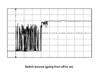
Figure 3 The problem switch bounce
We can solve the problem by add a “delay (10)”, it makes the system not working for this time 10mS.
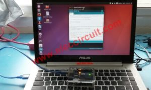
Then, we apply the USB to computer to upload code. As Figure 4 We are testing the Button become Toggle Switch using Arduino.
Figure 4
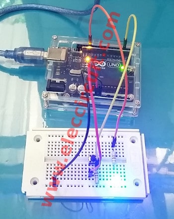
Next step, as video we try to press LED is ON Even if we leave it to the LED is still ON. But when press again LED is OFF and still status util we press button again.
Related Posts

Hi! My name is Aot. I like to play games. I’m 16 years old.
Now I rewrite article on our web with my dad.