Usually, an analog to digital converter circuit or A/D. Need to use a highly accurate device and too difficult.
But this circuit, The error of all devices does not affect the accuracy of the circuit. We just use the reference voltage only.
CR: https://simple.wikipedia.org/wiki/Analog-to-digital_converter
How it works
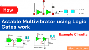
The CA3130 op-amp IC1 is assembled as the comparator circuit. Thus if the voltage at the inverting input less than the analog signal at the non-inverting input. The output will be “1” and when FF1 get pulse from the clock pulse generator. Which include of N1 and N2.

Schematic diagram of Analog To Digital Converter Circuit
While input D of FF1 is still “1” by result of IC1, so cause the output Q is also “1”. The CMOS switch S1 will close circuit, at the same time S2 open circuit. Thus, the capacitor-C2 is charged by the reference voltage (Vref), that through S1 and R2.
When the C2’s voltage same voltage at the non-inverting input, cause the IC1’s output will be “0”. But C2 still continues charging until the next circle clock into the circuit, then cause the output Q of FF1 is “0”, S1 open circuit, and S2 close circuit.
This time C2 will discharge through R2,R5 and S2 until voltage at C1 reduce lower than the analog input. And when output of IC1 is “1” again that next cycle, output Q of FF1 will be “1” again and the same operational continually.
Since the capacitor C2 is charged and discharged in exponential form. Thus the signal input is long times C2 will get the charging, and C2 will discharge in short times range.
This result cause output of IC1 has square waveform that duty cycle is proportion with analog input. However, the circuit is working properly, only the first input, C1 is charged up, the voltage across it is zero.
When switch to “Start” is pressed, Signal change will start,begin with set value to FF2 cause IC5 and IC6 that is counter circuit, start up both Ics acts as the pulse counter. IC6 will count all pulse, but IC5 will count while output Q of FF1 is “1” only.
When output Q12 of IC6 is “1” FF2 will be reset and changing will be end. The number of cycle at IC5 count will be proportional to the duty cycle from output Q of FF1. Which is related to the analog input..
If reference voltage is 2.048 fitted, IC5 will the 1000 fitted, same the input is 1V. By value a linear change of 1%. Because this circuit IC1 is used Ob Amps (Numbers LF357). Therefore, it requires a symmetrical dual supply well. For the frequency of the clock signal in this circuit can be changed. By changing the value of C3 (lowest 390 pF at 50 Hz).
Adjustment and Usage
For tuning the circuit to short circuit input to ground, then adjust P1 until the counting from IC5 is “0”. And the testing all by take the reference voltage into the analog input, at output of IC5 will must be “1” all pins (can count as 2047)
How to build
First of all, you need to buy all parts then make the PCB
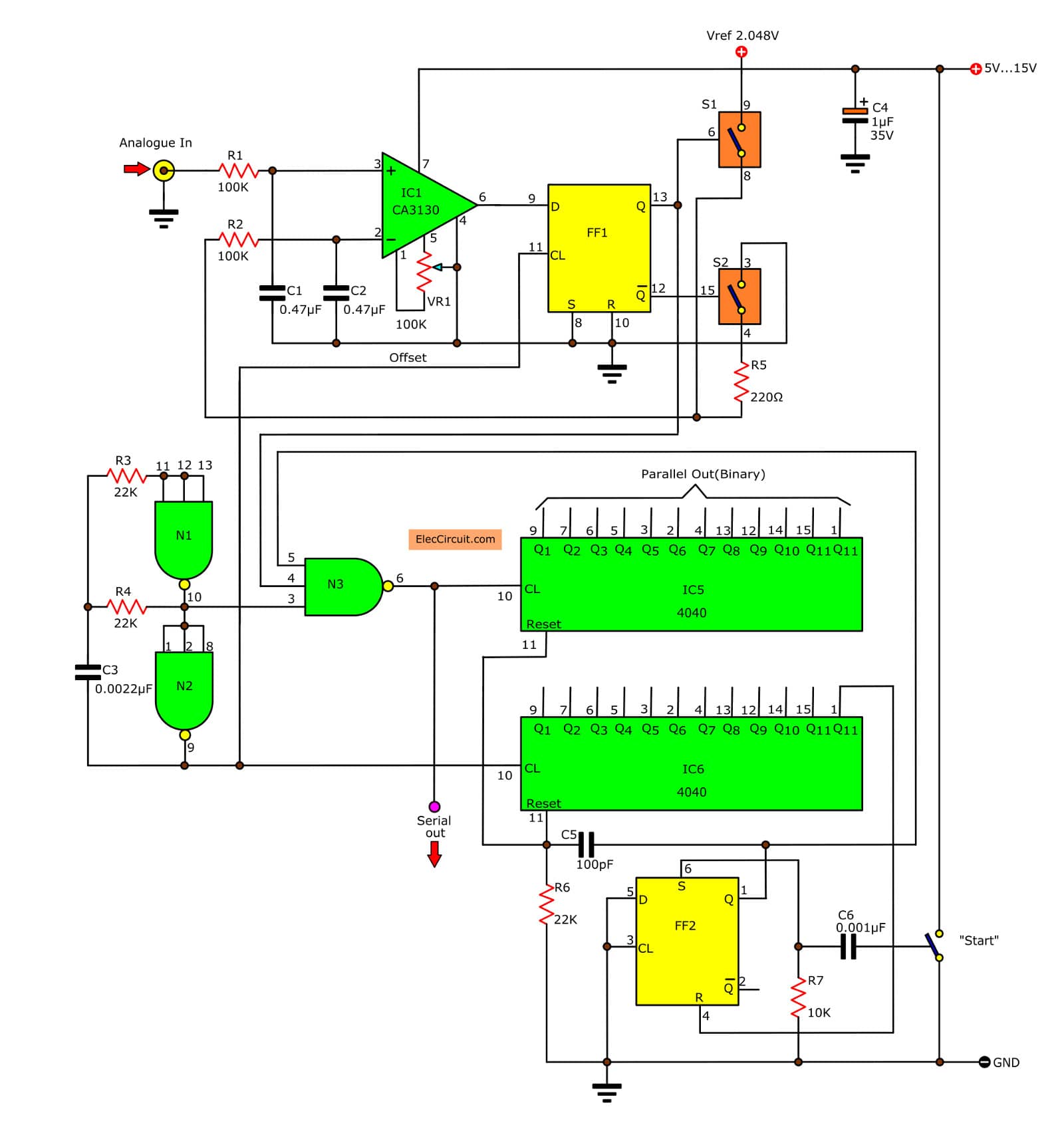
Fig. 2: The actual-size of Single-sided Copper PCB layout
Next, assemble all parts on PCB as components layout.

Fig. 3: The components layout of this projects.
Parts you will need
IC1: CA3130, Op Amp, BiMOS, MOSFET Inputs, CMOS Outputs, 15MHz
IC2: CD4013, CMOS DUAL D-TYPE FLIP-FLOP
IC3: CD4066, Quad Analog Switch/Multiplexer/Demultiplexer
IC4: CD4023, Buffered Triple 3-Input NAND/NOR Gate
IC2: CD4040, 12 Stage Binary Ripple Counter DIP-16
C1,C2: 0.47uF 50V, Ceramic capacitor
C3: 0.0022 50V, Ceramic capacitor
C4: 1uF 35V, Tantalum capacitor
C5: 100pF 50V, Ceramic capacitor
C6: 0.001uF 50V, Ceramic capacitor
ETC…
Is it hard? Sometimes you may use simple circuits work well for your work.
Simple Analog to digital Amplifier
The electrical signals from the transducer, Sometimes it is valued less too, For input to the circuit to convert signals from analog to digital.To achieve a satisfactory. We need a power amplifier, who can tell the strength of the input signal is simple.This can extend the input signal from the transducer is 10 times and 100 times.
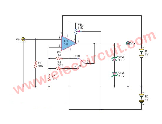
The circuit consists of op-amp IC1 No. 741, To give the appearance of non-inverting circuit, R1 is configured input impedance switches.In this the 75 kilo ohms, negative feedback circuit consists of R3 or R4 together with R2, which defines the gain of the circuit.
The gain of the circuit is equal.
R2 + R3 / R2 When S1 scroll at the top.
R2 + R4 / R2 When S1 scroll down below.
When the value provided in the circuit will gain about 100 and 10 respectively (actually supposed to be 101 and 10.1).
Power supply for this circuit requires two sets of power supply positive and negative, which was in the range of positive, negative 6 volts to the positive, negative 15 volts, in this value-add, subtract 9, because available with 9-volt battery immediately.

Related Posts


I love electronic circuit. I will collect a lot circuit electronic for teach my son and are useful for everyone.
Thanks.
Thanks Salim, Is it possible to share PCB details like Board file, Schematic or Gerber files for it.
Hi, Could you please try to improve the description? I cannot really understand much, which one is your native language? Maybe you can write it in that language and then I can try using some online translator. Thanks
Hi, How should I connect my resistive liquid level sensor to this circuit? Thanks