If you are looking for a simple power supply circuit with PCB. Here is how the 741 Op-Amp Power supply circuit works. For example circuits variable voltage regulator using IC-741.
It was a famous IC-op-amp for a long time ago. This still is useful.
I am always happy. When you see you get developed in electronics Here is a step-by-step Learning Op-amp in power supplies circuit design.
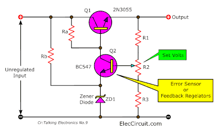
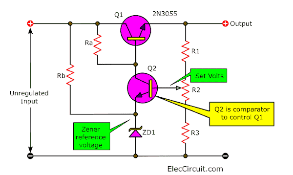
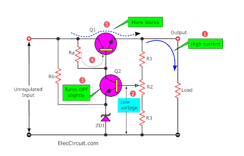
Transistor regulator with error sensor
We come to review previous knowledge. First a look at the basic transistor regulator version of an “error sensor”.
Then we will learn or see how an operational amplifier fits in.
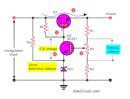
The circuit shows a series pass transistor 2N3055. It uses error sensor transistor BC547. See: wired to form a feedback regulator.
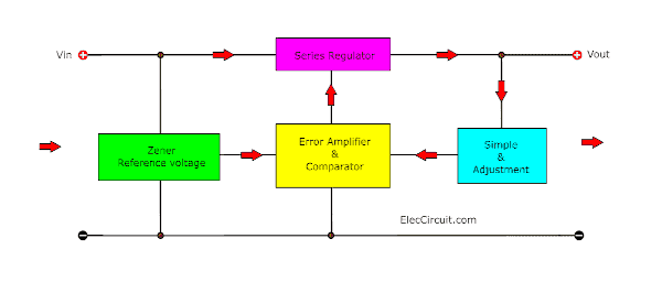
Look at a block diagram below. It is a good teacher to easily understand how this circuit works.
We may consider the series pass transistor work as a variable resistance.
So that at any stage it has an effective resistance. And there is a voltage dropped across the collector-emitter leads (C-E junction).
If the current through the load increases. Then, the voltage across the pass transistor(C-E leads) increases.
But the output voltage to the load would decrease.
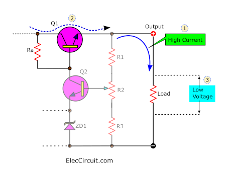
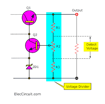
Three resistors R1, R2, and R3 form a voltage divider across the output.
While the center arm of the variable resistor R2 will detect this drop in voltage. [ Not the full voltage drop but still a voltage drop].
To begin with, Q2 is a comparator. It will compare the accurate Zener reference voltage with the “set voltage; to control the voltage on the base of Q1.
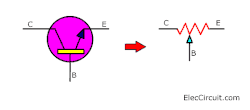
Look transistor as error voltage sensor working
So what. Let’s see it. When we apply the power to the circuit.
The Q1 is fully turned on via Ra. Then, the output voltage rises. Until the Q2 turns on via the voltage on the slider of R2.
The BC547 is making a voltage drop between collector and emitter leads. And, this is added to the Zener voltage.
The base of the 2N3055 “sees” this voltage and produces an output at the emitter which is 0.6V less than the base voltage.
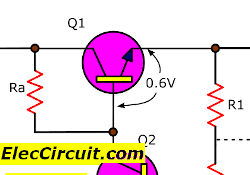
This output voltage via the BC547 and the 2N3055 transistor may adjust its collector voltage. Until a state is produced. Which is stable for the setting of R2.
If the load-current increase. The voltage on the base of Q2 falls slightly. And, Q2 turns OFF slightly.
So that the voltage on the base of Q1 rises via Ra. Q1 turns ON higher to increase the output voltage.
In short.
The “error amplifier” Q2 is well named. It detects any difference between the Zener voltage & the reference voltage(know as the error signal).
If the error signal changes the transistor amplifies this signal. And feeds it back to the base of the series pass transistor to adjust its effective resistance.”
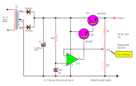
Zener diode & OP-AMP regulator
This is a voltage regulator using the Zener diode and OP AMP. The circuit is used for controls the voltage battery is very steady.
This circuit applies a very low current to about 1mA only.
Thus there is a ripple voltage of about 1 mV at input voltage changing between 10 to 30 volts. Like the circuit, the output is the fixed voltage of 8V.
How it works
We often use the Zener diode to make a fixed voltage regulator. Because it is so cheap and popular use. But It doesn’t is a very stable voltage regulator. As it has ripples too much and changes voltage when temperature changes.
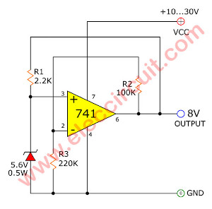
The voltage regulator using zener diode and OP AMP
In the circuit above, we connect the reference voltage to the input of 741 OP-AMP (popular ICs), to a non-inverting input and output of the circuit. This will is the same as the Zener voltage multiply with OP-AMP gain as below.
Vo = Vz * {(R2 + R3)/R3}
The advantages of this circuit have two reasons.
- We can use a Zener diode that a low-temperature coefficient (5.6V), to cause the output voltage to depend on the op-amp gain only.
- The op-amp input does not pull current from the Zener diode.
Thus, the Zener diode current is steady, then the resistor current is also steady. We do have the output as the real DC voltage regulator. And feedback to Zener diode again by R1, the current of Zener equal (Vo-Vz) / R1
Therefore: We have to select R1 in the current size of about 1 mA flow through the Zener diode. And maximum current flow into the output is about 15mA at the reference voltage.
Caution easily one: We use the DC voltage supply or unregulated to the circuit should have a higher voltage than the output about 1 volt.
Read Also: What is Zener diode? Its principle working and example usage
Parts you will need
- IC1: LM741 – OP-AMP
- ZD1: 5.6V 0.5W Zener diode
- R1: 2.2K – 0.25W Resistor
- R2: 220K – 0.25W Resistor
Using op-amp as an error sensor
The same error detection can be produced by an op-amp.
We use an op-amp instead of the error sensing transistor. Look below.
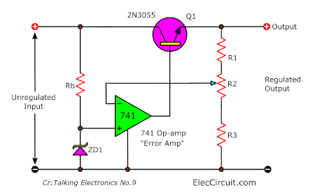
This is a basic 741 op-amp as error amp on the regulated power supply.
Recommended: How to use 741 op-amp circuit
Two points that we should learn.
- Two power rails for the op-amp are not drawn and it may be difficult to see how the op-amp functions.
- Remove Resistor Ra – why?
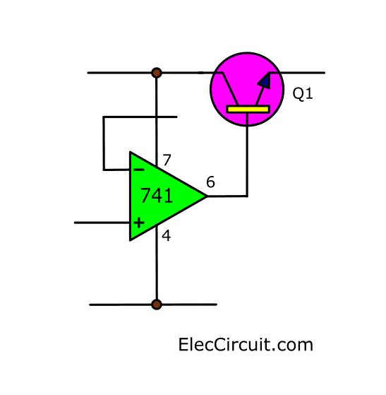
When the power rails for the op-amp are included. It is easy to see where the base of the 2N3055 gets its “turn-on” voltage from through the op-amp power rail & pin 6.
And this means Ra is not required.
When the circuit is switched on. The voltage entering the non-inverting input (+) turns the op-amp on fully to drive the 2N3055 into full conduction.
The output of the power supply rises. Until the feedback voltage from the adjusted control R2 reduces.
It will turn-on voltage from the op-amp & the output voltage settles to the set voltage.
Buffering the op-amp
We can use an op-amp to drive a 2N3055 directly. This will produce a power supply with a limited output current.
Here is why:
The op-amp can give about 25mA. This current will drive the base of the 2N3055. And If the current of a 2N3055 is 20.
The output of the power supply will be 25×20 = 500mA. To increase this current we need an amplifier as follows.
Power supply with current amplifying transistor Q2.
The output current of this circuit is 2A max. By helping of Q2 in the Darlington form.
Read other: Cr: Op-Amp power supply circuit working
Meet Voltage Regulator using Op-Amp and Transistor
This is a voltage regulator using op-amp and transistor. The fixed-voltage is 15V 400mA.
It has short circuit protection. Though ancient if you have the parts ready. You should try it.
Recommended: LM317 Power supply circuit
The Op-Amp Regulator with Series-Pass transistor. It is a linear regulator. It has load regulation better than the normal circuit.
The working of this circuit
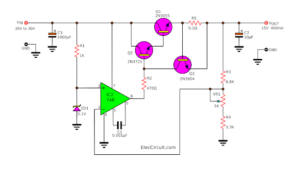
Here is 15V voltage regulator using Op Amp and Transistor.
First of all, The Linear 15V DC Regulator Circuit will converts an unregulated DC voltage between +20V and +30V to stable 15 volts 400mA.
Then, we use the IC-748 OP-AMP to control the stable voltage. The ZD1-5.1V Zener diode and R1 provide a reference voltage at pin 3 of IC1.
Recommended: What is Zener diode? Principle working and circuits
Next, the electrical current comes out of pin 6 of IC1. Pass the base of the Q2-transistor.
Which both transistors Q1-2N3055 and Q2-2N3725, and R2 are connected as a power-Darlington transistor for boosting up current output.
This circuit can give the current up to about 400mA only. But sometimes, the output has too many currents.
So we need the protection circuit with Q3-2N3904. While overload current, it causes a voltage level across R5-0.1 ohms is 0.6V. So B-E of Q3 is biased, it turns on.
Keep Reading: Power Supply Splitter circuit using Op-Amp
Then, both Q1, and Q2 stops working, and the output is low voltage or load safely. We hope this circuit will improve experiences and understands the Voltage Regulator system well.
The others detail, friends can see in the circuit.
Read Also: Learn Fixed voltage Regulator Working principle
Parts Will you need
- IC1: LM748, Operational Amplifier
- Q1: 2N3055 or equivalent 100V, 15A, 115W, >2,5MHz NPN transistor
- Q2: 2N3725 or equivalent 50V,1.2A, 0.8 W NPN Transistor
- Q3: 2N3904 or equivalent Transistor General Purpose BJT NPN 40V 0.2A, TO-92
- ZD1: 5.1V 0.5W Zener Diode
- C1: 0.001 uF 50V Ceramic Capacitor
- C2: 10uF 35V Electrolytic Capacitors
- C3: 100uF 35V Electrolytic Capacitor
0.25W Resistors tolerance: 5% - R1: 1K
- R2: 470 ohms
- R3: 6.8K
- R4 – 3.3K
- R5 – 0.1 ohms 5W Resistors tolerance: 5%
- VR1 – 5K Trimmer Potentiometer
Build 0-30V 1A Variable Power supply using op-amp
We have many simple variable power supply circuits. Here is another idea. If you have old components in your store. You can turn to use it again.
This circuit can give you many things. First, the output supply voltage range: 0 volts to 30 volts.
Second, the output current maximum: 2A (requires 2A transformer). Third, Overload protection with LED display.
How this project works
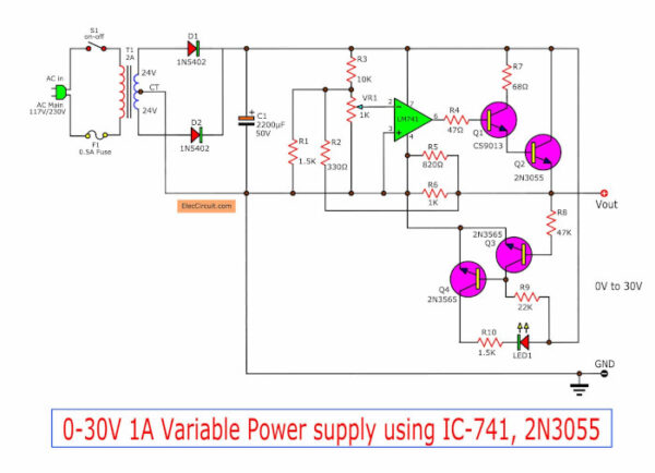
Look in 0-30V, 1A, Variable power supply using IC-741,2N3055, and 2N3565
First, the input of the circuit plugs into the wall and converts the high-voltage AC supply in your home into a safe, low DC voltage for electronic devices.
The 220V AC mains voltage from the power core comes into the transformer via a fuse to protect the circuit.
The transformer converts high voltage AC to lower voltage AC, 26V CT (26V-OV-26V).
Second, both power diodes are full-wave rectifiers to rectify the AC to DC, varying DC voltage.
Then, the 1000uF-filter capacitor smooths it into a steady direct current (DC). This is the unregulated power supply, at a DC voltage of about 36V.
Third, This circuit has a filtering regulator. They include many components.
The IC-741 keeps the stable output voltage. The potentiometer-1K adjustable output voltage.
The IC-741 makes a constant voltage out of pin 6.
Then, it flows from the base of the CS9013 driver transistor to a 2N3055 power transistor with a high current up to 2A.
While it is working, it is too hot so it requires a large heatsink.
Here are a few related posts you may find helpful, too:
- LM317 Low dropout regulator 5V 2A using TIP41
- 0-50V 3A Variable power supply
- Simple Variable power supply circuit 0-30V 2A
How to build
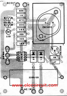
PCB layout
Note: This circuit maybe just a circuit idea. If you will build it. I think it has another choice. It is suitable for you. 0-30V 3A Variable Power supply
Download This Post
All full-size images and PDFs of this post are in this Ebook below. Please support me. 🙂


Related Posts


I love electronics. I have been learning about them through creating simple electronic circuits or small projects. And now I am also having my children do the same. Nevertheless, I hope you found the experiences we shared on this site useful and fulfilling.
Can I use 24v, 2.5 amp transformer
Very Good Explanation!!!!!!
Hi my friend
Thanks for the feedback.
Hello Sir I need a circuit for 10A ,310V DC supply can u help me this??
Hello Ananthababu,
Thanks for your visit to my site.
Now, I do not have that circuit as you want. If you have a new or update I will email you. Please subscribe with me.
Have a good day.
hi how can i donate to this projectY?
thanks for all
Hello tural,
Thanks a lot. Your text makes me smile.
I am happy that this post is useful for you.
I appreciate you donating to me. Which way is the most convenient for you?
https://www.buymeacoffee.com/eleccircuits
I drink coffee every day, buy me some coffee.
Thanks again.
Apichet Garaipoom
GOOD SITE FOR ELECTRONICS
Hi,
My dad and I are very pleased that you visited our website. But I am learning the Electronic It is quiet hard for me. I will try., 😃