Here are 3 DC polarity tester circuits. Why should use them? Imagine you are repairing a Car, Automobile, or motorcycle. And the electrical system in the car is what headache for you.
Checking some point connecting is a positive voltage or a negative voltage. Even short, open and loose. Using a normal multimeter. May be difficult or not comfortable.
Using these circuits is an easy, fast, and cheaper circuit. Because of a few parts.
In this post, I will show you 3 circuits. Below
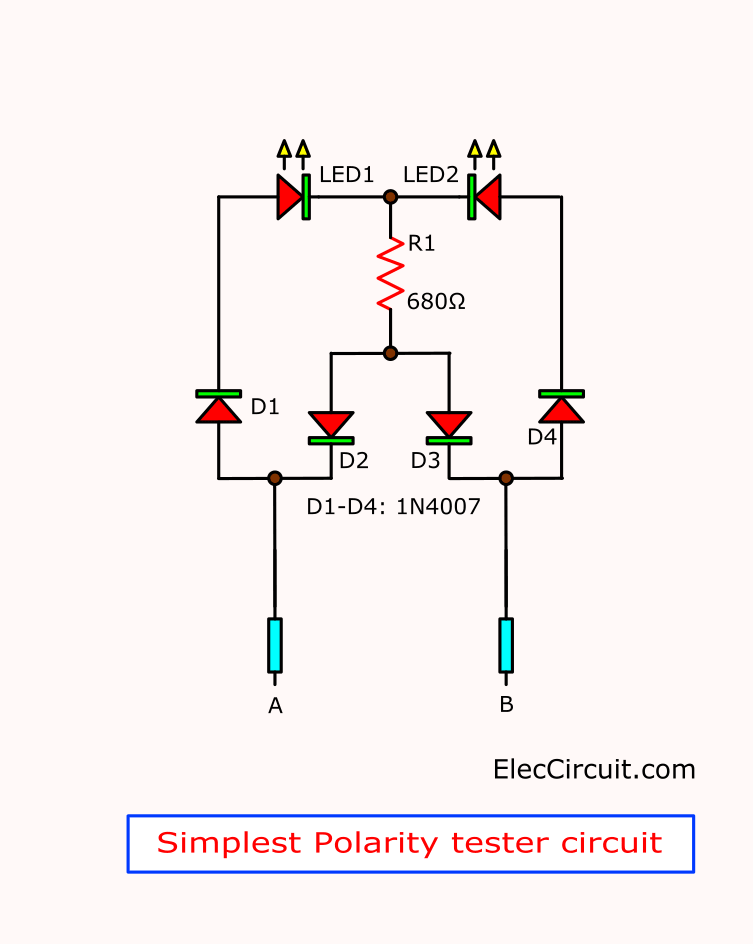
Simple Polarity tester
We will start with the simplest circuit. Look at:
It is easy but interesting. With 7 components only.
Working of polarity tester circuit
Let me explain to you how it works. Step by step:
Look at the Block diagram below. It helps you to read less. But understand more.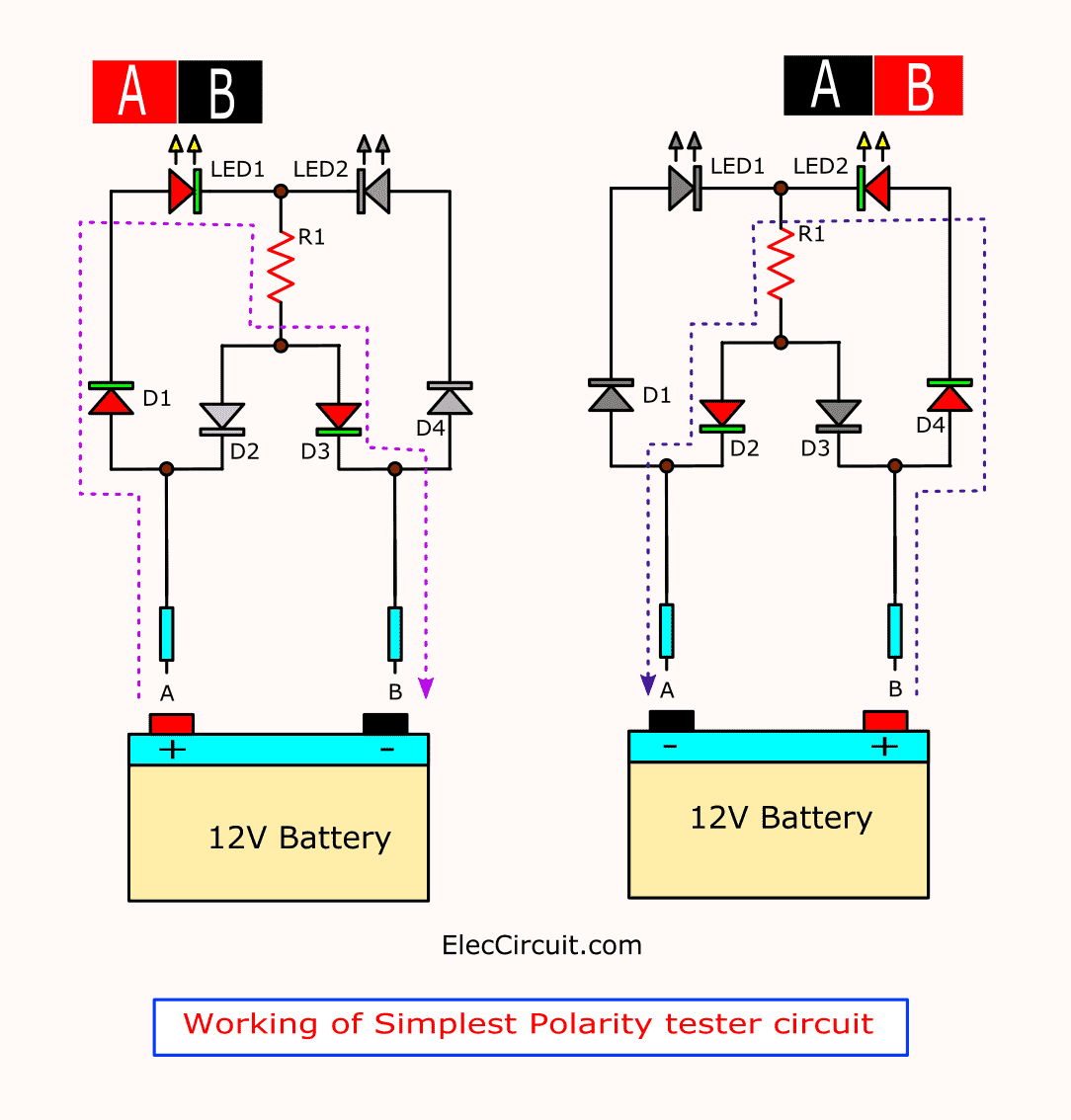
Take the A and B probes to both terminals of the 12V battery.
There is 2 case:
Image First, LED1 light up but LED2 goes out. Why?
Because the A probe connects to the positive And the B probe connects to the negative.
Since, the positive current flows D1, LED1, R1, and D3 to the battery.
Image Second, LED1 goes out but LED2 glow.
In contrast, A probe connects to a negative voltage. And B probe connects to positive voltage. Since the positive current flows through D4, LED2, R1, and D2 to the battery.
This circuit is so easy. But some want more option.
I like to Improve.
Simple polarity tester using 555
We ever use the 555 timer IC many times. You may be bored to hear Its advantages. Okay, you know it.
Let’s use it.
Look: in the simple circuit.
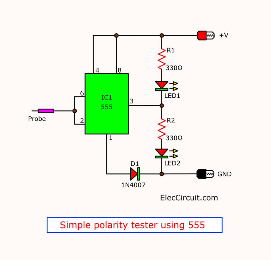
Here is step by step process.
It has a fewer part than above transistor version.
Because of the many components inside 555.
The wide voltage of power supply from 5V to 15V. Mean that can test 6V and 12V easy.
How to use this circuit is similar above. You just connect both probes to the battery then test any point in the circuit.
When probe at pin 6, pin 2 get a positive voltage. IC555 gives a negative voltage. Makes LED1-Red glows. But LED2-Green goes out.
In contrast, The probe gets a negative voltage. IC555 gives positive. It causes LED1 goes out. And LED2 Green light up.
R1, R2 limit safe current for LED1 and LED2
D1 protects a wrong polarity power supply.
Even more importantly. Let’s improve.
555 Polarity & Car Electrical tester circuit
Not only check polarity in car or automotive. Let’s make automotive probe tester circuit.
Sometimes you need to check error point:
- How to find an open circuit in a car.
- Find loose connecting in the ground all any terminal.
- Is it short circuit with the positive battery?
- Or short circuit with the negative batter?
- Is it connect with the positive voltage via any resistor?
- Or connect with the negative voltage via any resistor?
- That point connect has constant voltage half of 12V battery
You probably wonder Can this circuit solve these problems?
Yes, it can do that. This circuit may make you smile.
Sound good, doesn’t it?
How it works
We just modify and add more components of the second circuit above.
Let me explain step its process:
The principle of this circuit is producing a frequency to drive a LED display with various conditions of the probe.
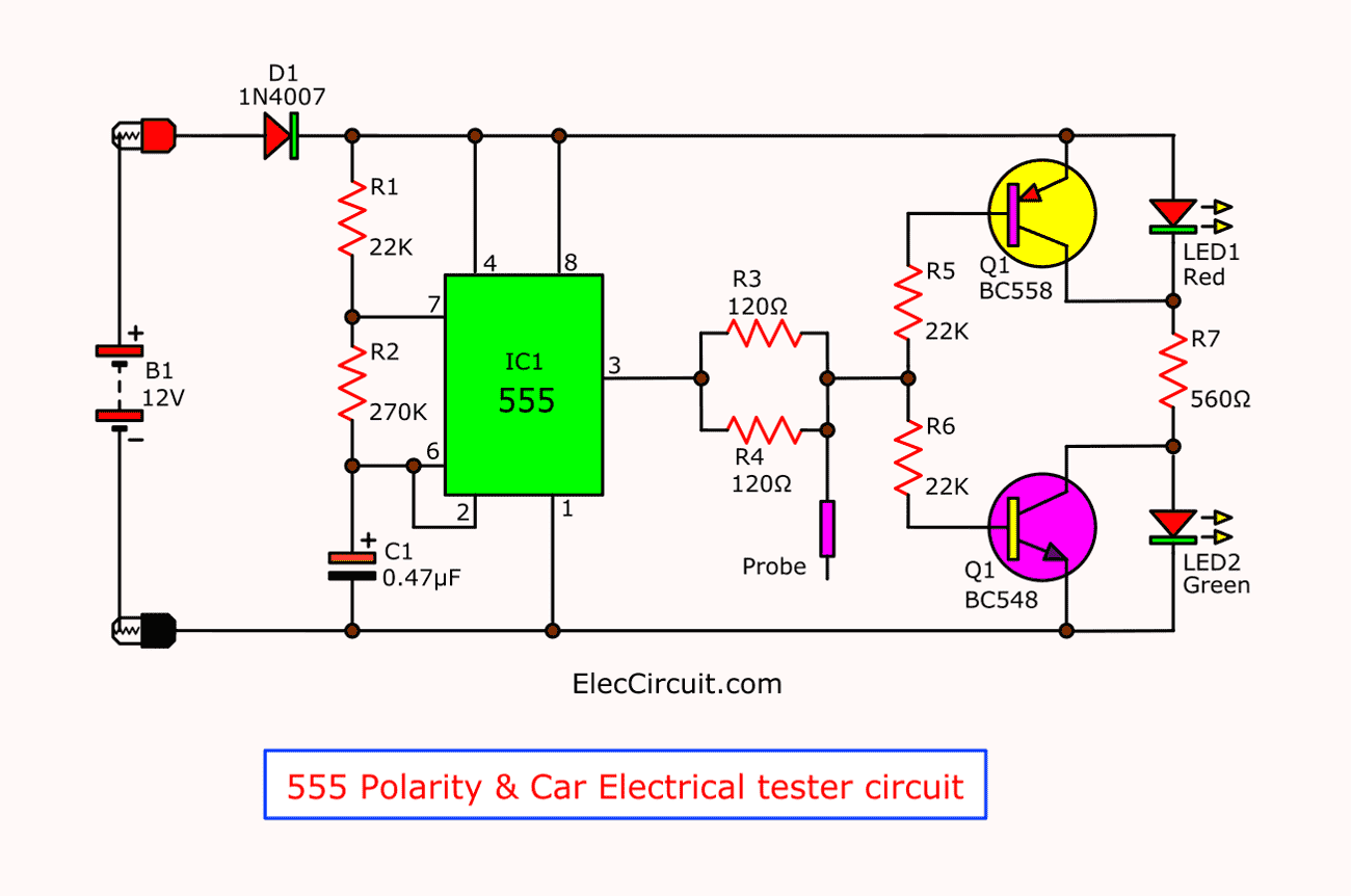
For instance, we touch the probe to:
Positive or Negative voltage, or nothing connection. Both LEDs will display in different.
Then, let’s see the operation of each component.
First, Diode D1 connect with positive. To protect a wrong polarity for IC1.
IC1-555 is a frequency oscillator circuit. We called astable multivibrator. This frequency is a square waveform about 4HZ. And, we set this with the value of R1, R2, and C1.
Last, output frequency comes out of pin 3 of IC1. To the base of Q1 and Q2. With R3 and R4 to limit the output current of IC1.
In addition, both R5 and R6 will limit a bases current of Q1 and Q2 in order.
We set both transistor Q1 and Q2 like a switching mode. And, Uses R7 is a current limiting resistor through transistor and LEDs.
Both LED1 and LED2 will indicate the status of the probe.
Shall I explain working in 6 cases?
Case 1: Open circuit
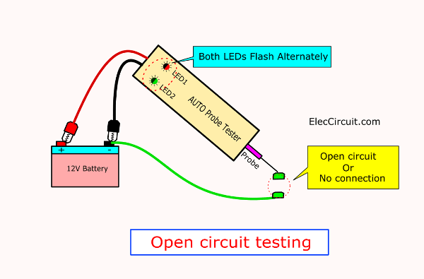
If your probe is nothing connected. Or it is open circuit status.
Both LED1(Red) and LED2(Green) blink alternately.
Because both Q1 and Q2 get DC pulse 4 Hz signal from IC1. When it is “high”. Make Q1 stops. but Q2 runs. In contrast, if it is “low”. Make Q1 run, but Q2 stop. They work alternately.
Case 2: positive connection
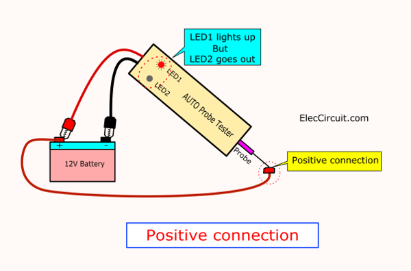
If this point gets positive. LED1 will light up, but LED2 goes out.
Because Q1 stop work. But Q2-NPN transistor runs.
Case 3: Negative connection
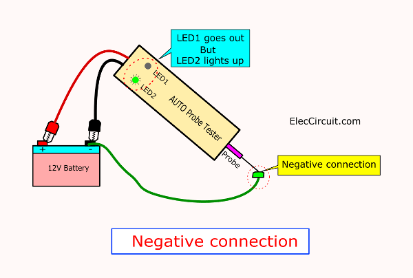
If this point gets negative. LED1 goes out. But LED2 glows.
Because Q1PNP transistor gets a negative voltage. So, Q2 stop work.
Case 4: Loose Positive connection
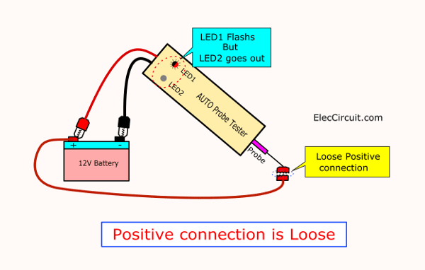
If this point connects to positive through resistance about 15 ohms to 400 ohms. It means the connection point is not tight. Makes LED1 flash up. But LED2 goes out. Because it gets a positive voltage not stable (loose point).
Case 5: Loose Negative connection
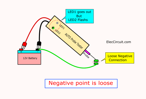
In contrast, this point connects to negative through resistance about 6 ohms to 800 ohms. It means that loose connecting with the negative.
Makes LED2 flash up, but LED1 goes out. Because it gets a negative voltage not stable with a loose point.
Case 6. Half battery voltage point
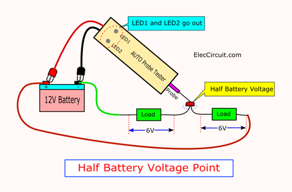
If that point has voltage is half of the battery (about 6V). Both LEDs will go out. Because Q1 and Q2 work at the same time.
You may also like these:
Parts you will need
Q1: BC558, 0.4A 40V PNP Transistor
Q2: BC548, 0.4A 40V NPN Transistor
IC1: NE555 or LM555 Timer IC
C1: 0.47uF 50V Electrolytic Capacitor
D1: 1N4007, 1A 1000V Diode
LED1: Red LED 5mm
LED2: Green LED 5mm
0.25W Resistors, 5% tolerance
R1, R5, R6: 22K
R2: 270K
R3, R4: 120 ohms 0.5W Resistor
R7: 560 ohms

Related Posts

I love electronics. I have been learning about them through creating simple electronic circuits or small projects. And now I am also having my children do the same. Nevertheless, I hope you found the experiences we shared on this site useful and fulfilling.
Very funy!
simplest polarity tester needs only with two LEDs and one resistor!
Thanks for your comment. LOL!
At the time, I was just learning about Diodes so I used them in this article.