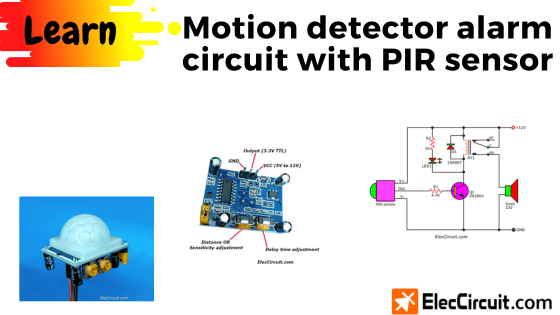
If you have your own private space and do not want someone to intrude, this motion detector alarm circuit will definitely reduce your worries.
Imagine there was a big bear coming in behind your house. Then the siren alerted, and the big bear got scared and ran away. Thus, you and your family are safe.
Isn’t it sound great? If you are interested in simple circuits, you can easily do so. Then these circuits will also be a piece of cake for you.
There are many ways to experiment with electronic circuits. But I suggest alternatives—simple and economical methods. And you can make the right choice according to your situation.
How it works
When a human or any warm-blooded animal comes within a radius of about 3 to 5 meters. This circuit detects them and sounds an alarm with a siren for about 30 seconds.
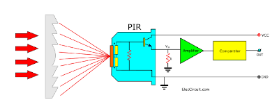
First, let’s convert the idea from above into a more easy block diagram.
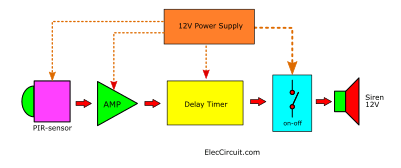
This block diagram is not too difficult, and we can use it as a broad process-by-process guideline for our circuit design.
- The 12V Siren is an alarm-sounding device. It is easy to find, cheap, and you can choose the size (watts) you want.
- When we use a 12V load (Siren), we should also use a 12V power supply; it should be easy to design.
- The on-off switch block is a controller for the siren, which consumes more power than other devices in the circuit.
- The Delay timer block is the part that extends the duration of the siren sound, even after the bear had ran away.
- The AMP (Amplifier) block is the part that amplifies the signal from the PIR sensor to further increase the signal strength.
- The PIR sensor is like a magic eye that keeps watching out for the bear instead of us. The new component that we have to learn.
What is a PIR sensor?
It is quite complicated. So instead, we are going to learn its very basics to use it well in general work.
The PIR stands for Passive Infrared; this device will detect infrared radiation from an object through a light-gathering device and send it to the Pyro Electric, which converts the heat energy from infrared radiation into electrical energy. Even with only a small amount of infrared, the PIR can still detect infrared radiation and temperature.
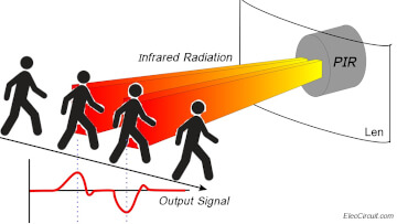
The PIR is usually included in the PIR sensor, also known as the PIR Motion Sensor. It will allow you to sense motion, almost solely to detect whether a human has moved in or out of the sensor range.
They are small, cheap, low-power, easy to use, and do not wear out.
The PIR Motion Sensor is commonly available as an already-made module.
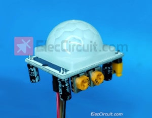
It has built-in circuits, including Amplifier and Comparator, making it more convenient for us to use.
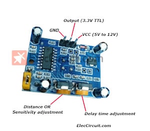
I chose to buy Infrared PIR Human Motion Sensor Detector Modules No. HC-SR501 due to their cheap price and average quality.
The output is a TTL digital signal, with 3.3V = “high” and 0V = “low”.
The feature
- Infrared sensor with a control circuit board
- The sensitivity and holding time can be adjusted
- Working Voltage Range: DC 4.5V- 12V
- Current drain:<60uA
- Voltage Output: High/Low-level signal:3.3V TTL output
- Detection distance: 3–7M(can be adjusted)
- Detection range: <100°
- Delay time: 5-200S(can be adjusted, default 5s +-3%)
- Blockade time: 2.5 S (default)
- Trigger: L: Non-repeatable trigger H: Repeat Trigger (default)
- Work temperature:-20-+80°C
- Trigger Method: L unrepeatable trigger / H repeatable trigger
Advantages of this module
It is small, cheap, low-power, easy to use, and does not wear out easily. That is why we often find them in appliances and gadgets used indoors, among many others.
We can use a 12V power supply for this, still within its recommended voltage range of DC 4.5V to 12V.
There is also a delay time function built into this module; the time delay can be adjusted to up to 200 seconds. This is enough, as we only need 30 seconds. So we do not need to build an additional delay timer circuit.
We can easily adjust the time delay in this module itself, as shown below.
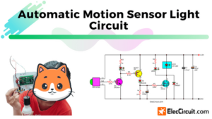
Turning it into circuit diagram
Next, we will put together a circuit according to the block diagram above.
The AMP (Amplifier)
But first, we would need to increase the output voltage of the PIR Motion Sensor Module to 12V from just 3.3V. Because we are using the 12V Siren.
There are many ways to do it, but we chose to use the transistor as a switch. It has a simple concept: by turning off (OFF) or turning on (ON) a load that uses 12V with a control voltage level of 3.3V.
As shown on the circuit below.
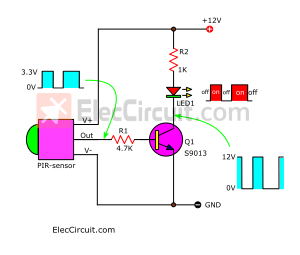
The output current of the module will flow through R1 as a biased current to the base of Q1. It causes Q1 to conduct current or turn on and drives a main current through R2 and LED1, lighting it up.
The LED1 will turn on and off according to the PIR sensor’s output.
The on-off switch
We chose the relay in this section because it has been easy to use and we are quite used to it.
See the circuit now with the relay.
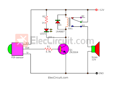
The relay’s coil will also be working as a load for the transistor; the transistor drives current to it. The relay (RY1) will turn on and off as the PIR sensor does.
The high current from the power supply will flow through a contact C to NO of RY1 through the siren to GND, completing the circuit. So, the siren emits a loud noise.
D1 protects against negative spike voltage that may be caused by the coil of the relay. It could have damaged the transistor and IC.
Simple 12V 1A UPS circuit
We need to have this circuit working all the time, even during power outages, so the power supply circuit must have emergency backup battery systems.
The circuit below is a 12V/1A UPS circuit; it is the simplest one. If using a siren of less than 10W, a 1A power supply can be used.
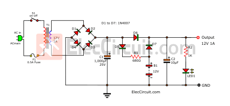
This circuit is both an unregulated power supply and a simple charger.
In a normal state, the transformer will convert a high-voltage AC main to a low ACV of about 12 volts. The S1 is a power switch for this circuit, and the F1 will protect against too much power.
The bridge rectifier (D1 to D4) will rectify the voltage from AC (alternating current) to DC (direct current).
The filter capacitor C1 is used to smooth up the pulsating voltage from a rectifier to a steady direct current (DC).
Currently, the voltage at C1 is DC, but the voltage rises to about 17 volts.
From this simple formula: DCV = ACV x 1.4
= 12V × 1.4
= 16.8V
Then this current flows through D6 to the output, lowering it to about 16 volts DC at the load. But this voltage cannot flow to the 12V battery because it is blocked by D7 in its reverse bias.
At the same time, some current flows through D5 and R1 to charge B1. Keeping the battery at full current all the time with a very low charging current or a floating state.
On the other hand, when the power goes out, battery power flows through the D7 to the load instead. But it cannot flow back into the unregulated power supply because it is blocked by D6.
Other components
- LED1 indicates the power on this circuit.
- The R2 sets the safe current for LED1.
- The C2 filters the ripple voltage of the output.
How to increase the current
But if you want more output current, you need to change your transformer to the higher-current one to match your desired current.
As well as changing the diode current to match that of the transformer’s current, you also have to increase the capacitance of the capacitor.
For example,
For the 2A output current, we would need at least a 2A transformer, 1N5402 diodes (D1-D7), and a 4,700 uF 25V capacitor (C1).
Conclusion
All of this is to learn how to use the PIR motion sensor by creating a simple project with it, which is very good. Currently, it is a simple and very cheap module.
In the future, we will apply it to other applications, such as automatic on/off systems to save electricity, and so on.
Get This
All full-size images and PDFs of this post are in this Ebook below. Please support me. 🙂

Related Posts


I love electronics. I have been learning about them through creating simple electronic circuits or small projects. And now I am also having my children do the same. Nevertheless, I hope you found the experiences we shared on this site useful and fulfilling.
PIR Sensor required for inst/test/comm at west bengal.Kindly send your tech detailed with price offer for approx 100 nos.
Niroj
hye i’m want to use this for my school project and i was wondering if you could explain to me further about the circuit. can i change the siren to maybe a lamp? and what id the use of the LED?
Remove relay and put pilot lamp 9v to replace. For led series with resisitor 330 ohm 1/4w with one led
hi, this is for my project.. may i replace the siren into LED? are the schematic still the same?
i need to the the operation of the circuit…
I want to use this ckt but not response properly.what is the code of motion pir sensor?
when i try this circuit…relay still not function..i try check the voltage across is 2++ volt..what happened.?
LED polarity is reversed
how can we increase time delay
i am using this circuit for my project. i have used a 12v o/e/n 57dp relay. the components are in good working condition. but when connected to circuit… its not working…
please help me..
Relay is not working
Me too also commented on january 15 2015…. that the circuit is not working…
but its working now after a few modification..
I have made this circuit successfully for my 4th semester mini project..
Please note the following to make it working..
1. Do not use the capacitor C1… as it delays the relay to activate
2. Use a 6v relay for better performance
3. Also the led is connect wrong… reverse the connection of the led…
4. It is better if we use a 12v 1A rectifier for input voltage
can you send circuit design..please
Hello Bro, Could you please send me this Circuit design
Yes, Please explain to us too. Knowledge is power.
I have made this circuit successfully for my 4th semester mini project..
Please note the following to make it working..
1. Do not use the capacitor C1… as it delays the relay to activate
2. Use a 6v relay for better performance
3. Also the led is connect wrong… reverse the connection of the led…
4. It is better if we use a 12v 1A rectifier for input voltage
Could you please send me the full Circuit design
Hello,
Thank you so much for good circuit. I have also made this circuit
successfully . But the led connection has wrong way .if give it up the positive side of led with motion sensor output line and give it other side of led with ground. so it will be succeed.
thank you
Hi, what is the voltage to give for pir motion sensor
This site is very good to know electronic user
Problem is if we remove the capacitor circuit wont be able to hold the alarm for 20 seconds
So this sucks ! 20 sec for start and 20 sec for end ?
Hi!
May i know what was the specific function of the transistor and diodes in the ckt above? please help advise.
does this sensor detects something present in how long distance?
what sort of things can this be able to detect and how does detection range changes according to obstacle?
Can you give design of this circuit for all components…pls
pls help me for design the circuit
Pliz guys can you help me with the equations for calculating R1 and R2
Pliz guy, anyone to help with the values of R1 and R2.
Hello Julius,
Thanks for your visit. I am happy you are interested in this circuit.
See in text again.
R1: 1.2K to 2.2K, 0.25W Resistor
R2: 1K, 0.25W Resistor
Thanks
hello Apichet can i get help from your circuit diagram please
Hi,
Thank you for visiting our website.
I would like to answer your question on behalf of my father.
Because I was able to experiment with this circuit with my father.
It’s correct. Do you need a PCB layout? Please tell us.
Thanks, 🙂
hello julius did you got what you wanted
I made this circuit but having problems, first is that there’s constant power to the relay, I hooked up a light to relay power out and it stays constantly on. Also the led doesn’t light up, used 1k resistor not sure if that’s the problem. Had to replace the 1n4007 with 1n5408 because of availability. Also the transistor gets really hot. Any ideas?
Hello Brian,
Please test again with this circuit. It is easy than before.
Yes, You can use 1N5408 diode instead of 1N4007.
Thanks
hello mr brian can you help me with the circuit diagram please
hello guys anyone with complete circuit can help me with the correct diagram