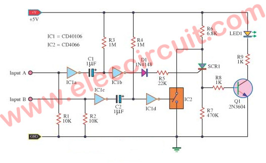
This is an On-off SCR control circuit with a logic gate IC. The behavior of the circuit. The SCR will turn ON when the input A gets the bias current. But the SCR will turn off if its input B gets the bias current.
Both inputs require the logic signal is “1” to control, and they will work alternately at different times.
How SCR conducts current
When input A gets a logic “1”. The IC1a will turn the logic into “0”. This makes C1 charges a positive voltage through R3.
For the IC1b gives the logic “1” at the output.
It is working as the monostable circuit to provides the pulse logic “1”.
Which it is controlled by the value of C1, R3 through the diode D1. It has just the positive voltage only that can trigger a gate of SCR. Using R5 limits the gate current to be not too much.
Recommended: How do SCR works and basic circuits
When the SCR triggers. It will keep conducting ON state. Although, the trigger voltage will change. The positive voltage will flow arose R6 through the anode and cathode of SCR. To be the voltage across R7, too.
Which it has the voltage is more than the voltage drops across R6. Because the resistance of R7 is more than R6. It makes Q1 is forwards biased to drive the LED lights up.
When we want the SCR to stop conducting or switch OFF. We need to enter the logic “1” to input B.
The C2, R4, and IC1d connect as the monostable multivibrator. They will generate the pulse logic “1” of 1 cycle. This logic comes to the controlled leg of IC2. Which this IC2( is an electronic switch IC.
See: CD4066 Datasheet (IC2)
The electronic switch will connect the anode of SCR to the ground. The voltage across the anode and the ground is 0V. This state, SCR will stop conducting immediately. The Q1 will be OFF and then the LED1 goes out.
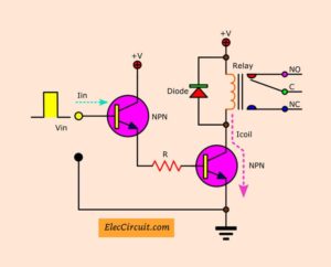
The voltage at the cathode can control other controller circuits. Which it is ON and OFF with SCR like the transistor Q1 circuit drive LED is on-off.
You may like to read these circuits too.
- How to rotate DC motor in both direction
- 3 idea Polarity & Car Electrical Probe tester circuit
- How does NE555 timer circuit works | Datasheet | Pinout
Parts lists
0.25W Resistors, tolerance: 5%
R1, R2: 10K
R3, R4: 1M
R5: 22K
R6: 6.8K
R7: 470K
R8, R9: 1K
Electrolytic Capacitors
C1: 1µF 50V
Semiconductors:
Q1: 2N3904, 40V 0.1A, NPN TO-92 Transistor
LED1: Red 3mm
D1: 1N4148, 75V 150mA Diodes
IC: CD40106 CMOS Hex Schmitt Triggers
IC2: CD4066 Analog Quad SPST Switch/Multiplexer/Demultiplexer
Keep reading:
- SCR DC motor speed control circuit using IC-CMOS
- Converts power supply to automatic battery charger using SCR-CA723
- Automatic night light circuit using SCR

Related Posts


I love electronics. I have been learning about them through creating simple electronic circuits or small projects. And now I am also having my children do the same. Nevertheless, I hope you found the experiences we shared on this site useful and fulfilling.
Hi all,
I just have rewriten this post. I hope my English to improve.
Hi I need same help please to design my work
Hello Blaze,
Please tell me what do you want to design.