If you are looking for a noise filter circuit. I have 2 circuit ideas for you. They use a transistor and FET as main components. So, easy to make. But I am very sorry for you. I cannot confirm they work well as you need. Because I never make it. But some friends want these circuit ideas. They are happy to try a lot of circuits. Thanks for visit.
Simple audio noise filter circuit for stereo system
In the receiver, stereo radio station. Usually, have more noise than listening in mono. Because the stereo system is split signal-to-noise ratio. (S/N) There level lower, cause interference, in mono with less. the because of phase noise of the 2-back phase. When combined into a mono signal was decreased by default.
How Simple audio noise filter circuit works
As a principle, the noise is high frequency, thus if both high frequencies are mixed together. The noise will go out while the sound still normally stereo system.

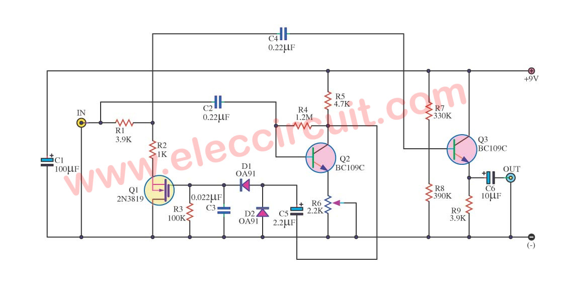
Figure 1 Noise Filter for Stereo system
Figure 1 includes the emitter common follower output circuit in series (cascade) in each channel. The high-frequency noise in 2 channel will be refuted, by through high pass filer include R3 to R7 and C3 to C5. This frequency is in 8 kHz range. When switch S1 close circuit and S1 open circuit the operation will stop but there are resistors R9 to R11 drop across S1 to maintain DC voltage level for capacitor C3 to C5. Thus when turning on switch S1 no sound “tup” out to the speaker.
The frequency will cut off without changing with add or reduce the value of C3 to C5, which if add capacitance cause frequency be low down.
Audio noise filter circuits using 2N3819 FET
When we said to Noise signal in an audio system. everyone not likes it, wants to get rid of it all. I also not like them too. However, we can use it to get rid of it. I use transistors. Because it is easy to find. And low noise. Friends try to see the circuit below.
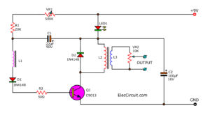
Noise Filter Signal using FET 2N3819
This is Noise Filter Circuit for filter the frequency disturbs all well. By using base type equipment the FET transistor number 2N3819 and Electronic part The other a little again. It can be usable economize with. By the circuit will decrease frequency tall signal more 20KHz well. Then can apply inside sound circuit well, and still have still can fine decorate filter noise level has as well.
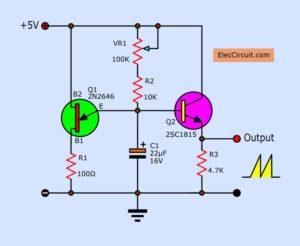
Clipping Amplifier circuit using BC109
This is clipping Amplifier circuit. It will improve a bad audio signal into the good sound.
Usually, when we turn up the music to the too high volume. The power amplifier cannot amplify the full sound signal.
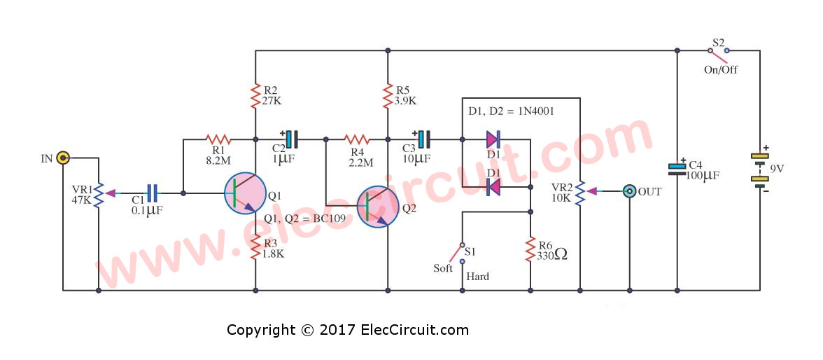
If enter the sine waveform, the output will be not the higher sine signal. It may be the sine wave that is cut off the top – bottom of the wave crest, may look like a square wave. Which the sound of the speaker is terrible.
But when we use this circuit. It will make the waveform of the signal is better. The peak to peak of the wave is similar to a sine wave.
We use the basic components, the transistors are main so the good sound and cheap.
Audio enhancement for analog amplifier
The CD / VCD player who uses the same listen to the audio quality is often poor. This is due to the IC Acting analog amplifiers. Most commonly used is the IC op amp.Cheap. Is a valuable slew rate low. It can not meet the immediate modification of the digital signal. The frequency response is not wide enough. Makes the sound come out with sharp and hard.
We need to fix with an analog output amplifier with high efficiency. And a filter in excess of unnecessary. To eliminate the sharp sound.So this circuit. Should select the IC op amp with high quality. To get a value LEWIS Garrett with a high and expensive. The circuit is not the number IC op amp to be used depending on demand.
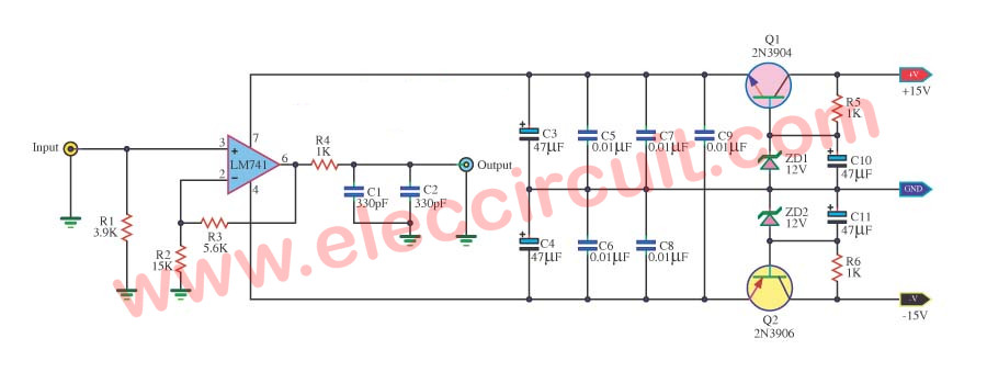
When raising the power supply circuit, the power sector through Direct loans isolates. Consisting of Q1, Q2, ZD1, ZD2, R5, R6, C10 and C11. The circuit Direct loans isolate the control voltage for supplying the integrated circuit is about 12V and-12V. The C5-C9 is a collector. bypass capacitor. Help in responding to high frequencies and reduce the leakage of the capacitor electronic highlighting of C4 and C3. When the input to the pin 3 bedroom inverse fitting IC1 to extend signal not to phase out the. Pin 6 and the signal part is fed back through R3 and R2. which is 1.3 times the growth rate C1 and C2 act to eliminate high frequency unnecessary.
This circuit is a circuit that extends the ordinary. The principle that the resistance of the circuit high input, to prevent the loading of the amplifier’s original CD. And a low output resistance, so they can drive loads easily. The sound quality that have come out that is based on the IC op-amps used IC op-amp should choose the high slew rate opamp.

Related Posts
I love electronic circuit. I will collect a lot circuit electronic for teach my son and are useful for everyone.