The Multi function digital frequency meter circuit 0-100MHz, is an instrument that can measurement many things in a single display with LED 7 segment 8 digit. The controls measures sector as well as the display is used a single master IC. Is A good IC of Intersil Corporation.
ICM 7226B
is a single IC at can acts as a very small external components. Can measurement frequencies from 0-10 MHz. When we put the frequency divider circuit (prescale) 1/10 the maximum frequency is 100 Mhz at measured one. In addition can measurement frequency of it, also can measure other things as well.
Special feature
– Can measure frequencies from 0-100 MHz.
– Can compare are frequency ratio fa / fb.
– can measure the period of frequency fa / fb.
– are the counter circuit from 0-10 million.
– Can test the oscillator circuit himself.
– Can hold data.
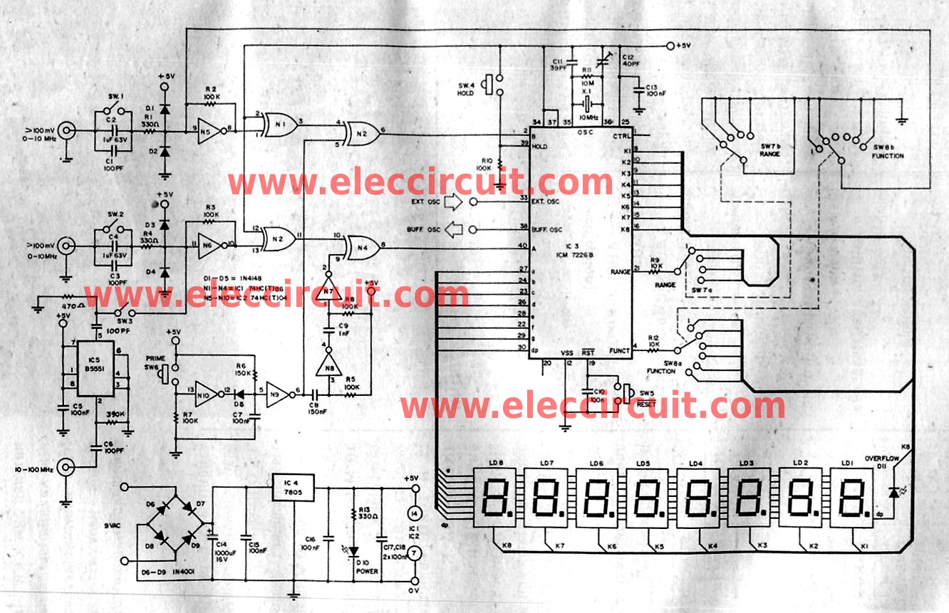
Figure 1 Multi function frequency meter 0-100MHz
How circuit works.
Start from the oscillator circuit which has Which has external devices works together the base time circuit inside the IC-3X1 working together with C1, C12, R11 are the oscillator circuit. By determine frequency of use at X1 is 10 MHz has C12 to adjust the frequency. This frequency value of 10 MHz May switch to 1 MHz by changing X1 is 1 MHz. By modify the CTRL circuit at pin 1 that use R 10K connected series with diode 1N4148 to pin K2 of display section.
The main input that use to measuring the frequency at an input A, but an input B is used compared with the measurement input A only. The selector switch (SW8) is used to select the measurement function. The switch-SW7 is used to select a range.
The function of both switch concluded as table below.
SW8 : Function
Position Function
1. (K1) frequency (fA)
2. (K8) period (TA)
3. (K2) frequency ratio (fA/fB) : fA>fB)
4. (K5) time interval (ta-tB)
5. (K4) unit counter
6. (K3) oscillator test
SW7 : Range
Position Accumulation Time/Cycle (s)
1. (K1) 0.01s/1 cycle
2. (K2) 0.1s/10 cycles
3. (K3) 1s/100 cycles
4. (K4) 10s/1,000 cycles
The working of the circuit on input C1 and C2, or C3 and C4 they use as the signal coupling circuit, by has SW1 and SW2 drop acrosss. If the switch SW1 or SW2 off Means measurement signal is fed into the AC.
But when they are in a position “on” it measure the DC signals. They R1, D1 and D2 serves as the R4, D3 and D2 which them serves as the R4, D3 and D4 are protect the signal were entered not have higher voltage levels than it could be dangerous. The circuit inside N5 and R2 works same with N6 and R3 are the signal amplifier circuit until the level is the TTL signal. Or there is changing of 0-5 volts. However, if the input signal is a TTL level. It will soon have a state of the buffer circuit.
The circuit on an IC N7-N10 and N3-N4 is used to measure the period of the signal from input A and input B or Time Intervals.
The switch SW6 (prime) for push before measuring the time Interval. The inverter N9 and N10 will make a narrow pulse to the input B. Then N7 and N8 will be delayed pulse switches these fed into input A. To help in these measurement period.
The SW4 serves as a Hold switch. When pressed this switch while the measurement output value is constant. Useful to remember the value to read. The SW5 Serves Reset circuit, for a reading of zero in the case functions measuring the torque Unit Counter.
They D6-D9 C14 working together with a rectifier circuit, there is C15 cut high-frequency interference. IC4 is the regulator circuit. D10 is LED show power ON. D11 is LED show the over flow.
IC5 is the prescale divided by 10. Properties of IC5, is divided better only the frequency of 10 Mhz-100 MHz only. If we want to measure frequencies above 10 MHz, must Enter the these signal into this input.And rocking the switch SW3 to position ON. If you want to measurement signals below 10 MHz must measured signal input A. Must be OFF SW3 as well.
Learn: How to use 555 timer circuits
Customization and Applications.
When the equipment has been completed, it is ready to be tested, turn the function switch to the oscillator tester circuit.
then we enter the power supply to this projects will see the LED power on glow. The frequency that show must be 10 MHz If this were to adjust the trimmer until it is 10 MHz. The customization have just only.
Then test a measurement frequency by rotating at switch to fA. Testing frequency entering to at input A. Input frequency is the frequency at we should get the value. Try to read that same frequency or not. If normal frequency is read out directly. Then the next step by turning the function switch to at TA. Reading value out the time period in seconds. If we know the value frequency of the input. We can calculate the values to be read out.
From the formula.
TA = 1/fA
Then test the measurement model to other.
The parts list.
Resistors 0.25 watt 5%
R1, R4, R13 330 ohm
R2, R3, R5, R7, R8, R10 100K
R6 150K
R9, R12 10K
R11 10M
Capacitors
C1, C3, C6 100pF ceramic type
C5, C7, C10, C13,
C15, C16, C17, C18 0.1 uF mylar capacitor
C8 0.15 uF mylar capacitor
C9 0.001 uF mylar capacitor
C11 39 pF ceramic type
C12 40 pF trimmer
C14 1000 uF 16V Electrolytic Capacitors
Semiconductor
D1 – D5 1N4148 or 1N914
D6 – D9 1N4001
D10 – D11 LED
LD1 – LD8 LED 7 segment common cathode
IC1 74HC86
IC2 74HC04
IC3 ICM7226B
IC4 LM7805
IC5 B5551
Others
X1 X-Tal 10 MHz
How to builds.
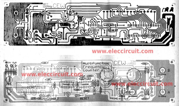
Figure 2 is PCB layout for you see as guide to makes.
But it is only basic not full how to build this projects.
Other Frequency Meter Circuits
- Cheap frequency meter circuit using 555 and CA3140
- VHF Dip Meter circuit
- Idea to build simple frequency meter from old calculator
Related Posts
I love electronic circuit. I will collect a lot circuit electronic for teach my son and are useful for everyone.
it is possible to measure single positive/negative pulse
thanks for help
Sir where can ic b5551 be foud, what is the purpose on ic b5551.
with which ic can be substituted.
Thank you
Ic5 extends the range of the counter so that it can measure frequencies above 10MHZ. There are a number of devices that will do this.
Wonderful work! Please Sir, I have a frequency meter with me that could not display frequency, but it can show light in some of the LEDs in the display. I do not know the component that could cause this. I checked the transistor but it did not correct it. The ICs in its circuit are: STC 89C52RC (40pin ic) and SN74LS07N. Thanks.