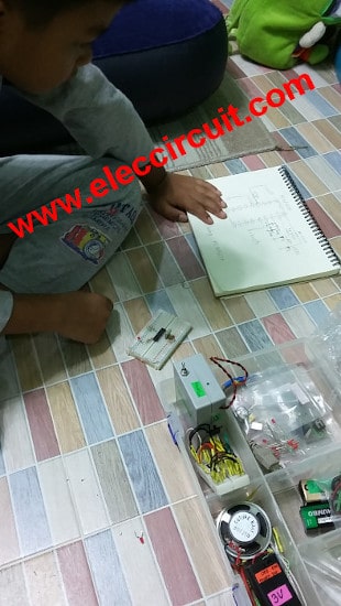
I will teach my son to learn Electronics as homeschooling. It is very good that the device Microcontroller is cheaper, find simple and easy to learn. I have not used it yet. Now, learn along with my son. We hope that learning this time, friends would have been helpful.
Microcontroller in everyday life
In everyday life, we often find the microcontroller. But it will be hidden in various electric appliances, Such as microwave ovens, washing machines, DVD, MP3, and more. The reason is that it has been used a lot because the work was well represented the electronics circuits.
When we want to change the operation of the electronic circuits. We need to design it all. Can not use the same circuit.
If you put the microcontroller used. We can change the work easily. By changing the program working within the microcontroller. Making its ease of design and flexibility of use as well.
Knowledge of the microcontroller
The microcontroller is the Electronic device that functions as a mini computer that takes control of electrical appliances, Internal memory can be changed easily, Using less hardware such as automation of the washing machine, the brain of the car and so on.
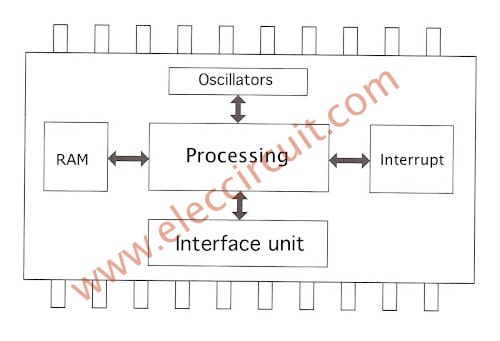
Micro controller Internal structure
_Processing unit
_Memory unit
_Interface unit
_Oscillator unit
_Interrupt unit
Processing unit does mathematical calculations or logic. This is complicated work, by the order in which the work is based on processing Programming code. Which is contained within the memory code that.
Memory unit serving store data Divided by into 2 different types of storage space, is RAM: Random Access Memory and EPROM: Erasable Programmable Read Only Memory.
Which RAM, we can change the data at any time and it was used to collect data, to store the variable in the calculation, by the data is lost when we stop power supply. The EPROM for storing Code to stop power supply, even though the information requires special treatment.
Interface unit is communication signals between the external device, and the microcontroller there are two types are
1. Digital I / O by receiving data, and transmits data by Digital signal.
2. Analog I / O, it will transmit and receive signals by Analog signal. Which is available on some models.
Oscillator unit serves to generate a clock signal, Using the circuit is connected to the microcontroller called oscillator circuit. The main device is Crystal (X-tal) to determine Execute time of processing, by will affect the processing speed of the microcontroller. The clock is also used to determine the speed Digital Series Communication signal and determining the frequency of Timer.
Interrupt unit serves to prioritize the work. In the case of microcontroller working Multitasking form. Which will greatly facilitate the programming?
The difference of microcontroller and Microprocessor
– Microprocessor It means a device, small processors. Functional processing only. The microprocessor communicates with By the digital signal to the Memory components. The size of the current signal is not high.
– Microcontroller Will resemble Microprocessor is a device for processing. But the microcontroller has the interface unit making can drive current to higher than the microprocessor a lot. the microcontroller, flexible design circuits connected to an external circuit and suitable for control rather than the microprocessor.
Test and microcontroller development
The Testing and microcontroller development, It will different from programming on the Computer. Which it uses input devices are keyboards and mouse, and output devices are the monitors as It is a device that changes seen clearly.
In programming for Microcontroller, we need to use a computer. Which will have a special program to convert programming code into Machine Language that we write to the Microcontroller tools. It then sends that data via a programmed microcontroller connected to the Computer. Then we will do a test run and customize programs to work well.
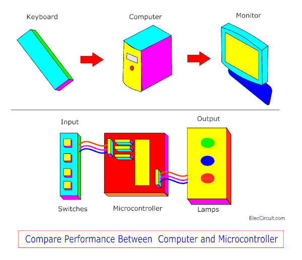
Compare performance between the Computer and Microcontroller
PIC16F627A Datasheet PIC Microcontroller
First time for PIC-Microcontroller
What is PIC Microcontroller
We should start learning with the Microcontroller that is easy programming. I and my son would start at PIC Microcontroller of Microchip. Which are easy to buy, cheap and a simple set of instructions?
PIC Microcontroller for the experiment
PIC microcontroller There are a lot of numbers. But we choose the PIC16F627
The PIC16F627A Datasheet is cheap, easy to use, ideal for learning programming.
The feature works as follows:
_ Working with voltage 2.0V to 5.5V
_ Running at 0-20MHz
– Can be programmed easily by using In-circuit serial programming
– Copy Data Protection
_Program memory size 1.75 Kbyte, Can be written and erased 100,000 times. Data storage for up to 40 years.
– Internal memory SRAM 224 byte
-Internal memory EFPROM 128byte Can write and delete it 1,000,000 times. Store data for 40 years
– Pin number at can be connected to external devices (I / O) 16 channels
– Cheaper
– Important: Good friends give free 6 PIC16F627A and all components for my son experiment and with USB pic programmer tools as the photo below
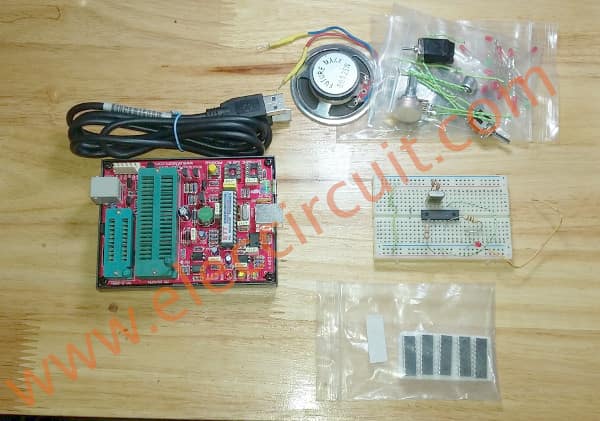
PIC16F627A and all components, and the USB PIC programmer FREE from a good friend
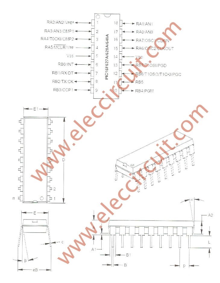
The pins and the shape of the PIC16F627
Hardware and Software
-Hardware is Equipment or materials that change shape or structureless you can touch them.
-The software is Equipment or materials that change shape and structure as much.
In experiments, I and son Hardware is the programmable tools and testing microcontroller circuit. The structure and exact functions.
Our software is the Program on the computer and source code as recorded in the IC. You can edit or delete rewritten at any time.
Hardware list
1. The programmable: my friend give me is USB port that can write many PIC microcontroller numbers and it is easy to use.
2. Experimental microcontroller circuit. When we finished recording PIC16F627. We will Experimental the various circuits. I will try to choose a simple circuit. To son learned easily. And appropriate for a beginner
Recommended:Learn Electronics with easy steps!
3. The connector circuit: Microcontroller circuit connections required are INPUT and OUTPUT which we choose a simple circuit. And can be easily Experimental on Breadboard.
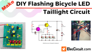
One LED Flasher use PIC microcontroller
This is microcontroller led flasher circuit using PIC16F627A as first PIC microcontroller learning of mine son. it is basic for really beginner.
Important issue,we have to make The PIC micro controller is easier. Children 8 years old, he does not understand the computer language at all.
My friends say that children should not play computer. He should try to build a lot of real electronic projects. I avoid to teach computer programming. It is difficult and tedious for him.
Thus, We start learning the micro controller with creating the one LED Flasher circuit using PIC16F627A.
It is a very simple circuit. In the past, I’ve recommended his son play Dual LED Flasher. by 2N2907
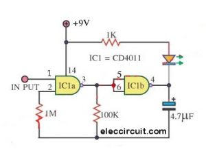
The circuit diagram
First of all, Assembling the components by the circuit in Figure 1 in to the Bread board, Very few devices. The PIC16F627A is important.
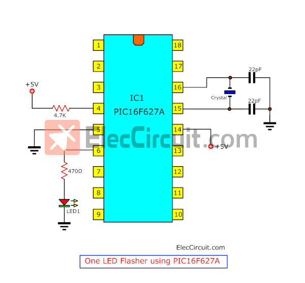
Figure 1 the circuit diagram
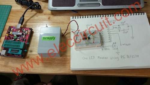
Figure 2 assemble all parts on bread board
All Software for PIC microcontroller
We get a pic programmer software CD for USB PIC programmer.
1. Driver for USB PIC Programmer is PICKit 2 Programmer of Microchip
2. mikroC compiler for PIC
Recommended: 1.5V 4 LEDs Flasher circuit using transistors
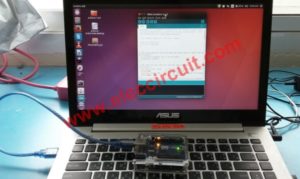
We install both software on Windows 7 OS computer.
PIC micro controller programming
Then we will write PIC micro controller on source code (human language), with C complier code. We perform the following steps.
1. Make new folder name : One_LED_Flasher
as Figure 3 for this project only.
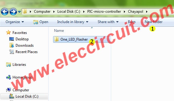
Figure 3 make new folder for this project
2. Make new project : step by step as Figure 4
(1) Click at new project
(2) Fill in name project
(3) Browse folder of this project
(4) Select Device : PIC16F627A
(5) Set clock : 3.579545 MHz as we use crystal in circuit.
(6) Set Device Flags: to Default
(7) Click OK to finish this step
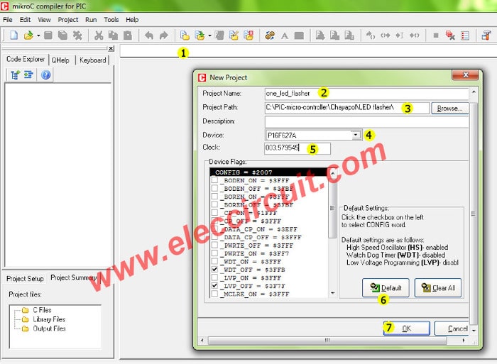
Figure 4 Setting new project option
3. Typing simple one LED flasher CODE into a blank board below.
main()
{
TRISB = 0xFE ;
while(1)
{
PORTB = 0x01;
Delay_ms(2000);
PORTB = 0x00;
Delay_ms(2000);
}
}
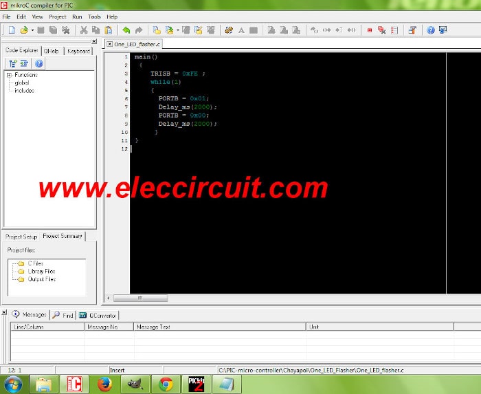
As Figure 5 Typing simple one LED flasher CODE
4. We will build Project…as Figure 6
(1) Click save all
(2) Then Click Build Project button (Ctrl+F9)
(3) Look at message text as Success
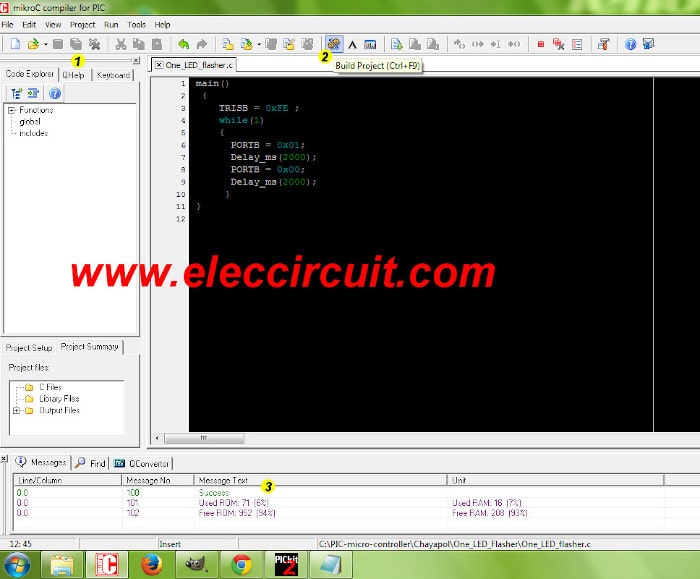
Figure 6 Build Project to get HEX code
5. Open the PICKit 2 Programmer to write HEX code (machine language) to PIC16F627A as Figure 7 we apply the PIC16F627A to socket on the Programmer tool. Next take the usb cable to computer. The LED power on display. We will look at “PICKit 2 found and connected. PIC Device Found. Show Device: PIC16F627A.
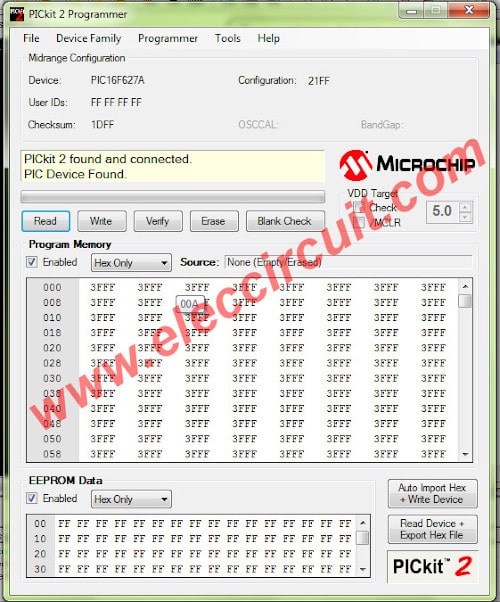
Figure 7 PICKit 2 Programmer ready to use
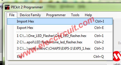
6. To import Hex code as Figure 8 we click File menu and Import Hex
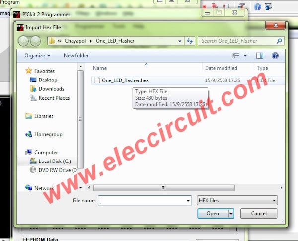
7. To select the One_LED_flasher.hex in this project folder as Figure 9
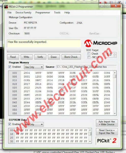
8. We look for “Hex file sucessfully imported as Figure 10
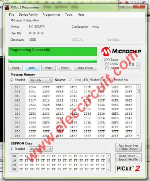
9. Click Write button then this system will write Hex code to IC. If finish will show “Programming Successful” as Figure 11
10. Apply the PIC16F627A that finish the programming to the bread board circuit again.
We will see that the LED flasher as Video below LED ON = 2 Second and OFF = 2 Second alternately.
11. We back to edit code again to change as below.
/// ON = 1S OFF = 3s
main()
{
TRISB = 0xFE ;
while(1)
{
PORTB = 0x01;
Delay_ms(1000); <==== For LED ON
PORTB = 0x00;
Delay_ms(3000); <==== For LED OFF
}
}
Then write the HEX code on PIC16F627A again. Next Experiments By step through.
Makes LED ON : 1S only and LED OFF : 3S
as Video below.
1000 = 1000mS = 1 second
3000 = 3000mS = 3 second
Note: Thus we can change long time for LED display with Code only, so easy and very accurate than RC times. For example 100S on old circuit we need to use capacitors Electrolytic about 1,000uF too very big!
We hope to learn the our PIC micro controller will be beneficial for you.
My son love Micro controller because it easy which it is not perfect just to have fun.
Two Led flasher PIC16F627
Today, We will try the PIC microcontroller 2 led flasher circuit using PIC16F627.
Because like this circuit Which we can set ON-OFF of both LEDs for easy, long and accurate.
Note: I intend to teach his son, love electronics, He likes to experiment with the electronic projects For the fun. Since this time He was 8 years old. I avoid hard content, We can apply for the simple microcontroller circuit only and modify them through a simple C compiler code. Do not need to understand all the work. It may be that he was wary of the microcontroller.
How it works
First time you should read at : this circuit
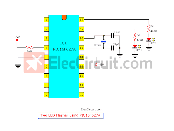
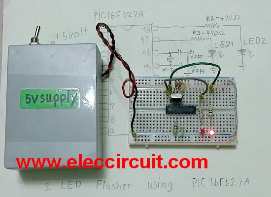
First of all, you must connect the circuit as Figure 1.
Second, Assemble all equipment into the breadboard as Figure 2
Then, we write Hex code into IC1 Please read how to here!
1. we type C+ code on mikroC compiler for PIC as below:
main()
{
TRISA = 0xFC;
while(1)
{
PORTA = 0x01;
Delay_ms(500);
PORTA = 0x02;
Delay_ms(500);
}
}
Parts you will need
IC1____PIC16F627A PIC Micro controller IC
R1_____4.7K 0.5W Resistor
R2-R3__470 ohms 0.5W Resistors
C1,C2___22pF 50V Ceramic capacitors
X-tal____ 3.579545 MHz crystal
LED1,LED2___LED as you want
The experimental results
When applying the 5 volts power supply to the circuit.
LED1 at Pin 17 will light up “ON” before for 0.5 seconds then it is OFF for 0.5 seconds.
And while LED2 at Pin 18 will light up instead for 0.5 seconds, next to LED 2 is OFF for 0.5 Second.
And LED1 back to light up again. the LEDs alternately flash ON and OFF about 0.5 seconds.
Both LEDs will flash equal 0.5S or 500mS as Code.
LED ‘s flashing modification
We try to modify the flashing of LEDs by changing to 500 to 3000 (or 3000mS or 3S), please look code below this.
1. LED1 will light up a 3 second, and LED2 will still light 0.5S As Video
Code modification for LED1
main()
{
TRISA = 0xFC;
while(1)
{
PORTA = 0x01;
Delay_ms(3000); <==== For control LED1 ON at pin 17
PORTA = 0x02;
Delay_ms(500); <==== For control LED2 ON at pin 18
}
}
LED1 turn on = 3S; LED2 turn on 0.5S
2. Then we edit code for LED1 is 500 again. And edit other code is 3000 as the code below.
Code modification for LED2
main()
{
TRISA = 0xFC;
while(1)
{
PORTA = 0x01;
Delay_ms(500); <==== For control LED1 ON at pin 17
PORTA = 0x02;
Delay_ms(3000); <==== For control LED2 ON at pin 18
}
}
Makes LED1 turn ON = 0.5S and LED 2 turn ON a longer stretch of time is 3 second.
LED1 turn ON = 0.5S; LED2 turn ON = 3S
Just as we can use it
From the top, we just experiment with changing the code number for mS time unit. We not change any hardware circuit and Not require any capacitor, making very precise timing.
Make PIC Programmer Box case with LEGO
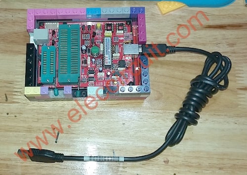
Here is LEGO PIC Programmer Box case with LEGO by my son
This circuit requires enough power supply. Do you have this one? If you do not have it. Look:Learn Many Power supply circuits
Related Posts

I love electronics. I have been learning about them through creating simple electronic circuits or small projects. And now I am also having my children do the same. Nevertheless, I hope you found the experiences we shared on this site useful and fulfilling.
hallo….
ich finde ihr controller learning very good.
pse moor from this thema…i will also learning!
many greetings
walter
Thank you a lot ! before this i had no idea on what i was suppose to do on a school project , but now i have a good head stars and even more knowledge i could possibly ask for .Thank you sooooo much, very helpful.
Hello, my dear friend,
I am so happy this morning to read your text.
I love to read your sharing.
God bless you always happy.