When we had to leave the place, then it is necessary to measure DC voltage.
If we carry all the time a multimeter. Feel too large. I think built Simple LED voltmeter circuit compact in a pen form. To the time required.
How the circuit works
In the figure 1 is circuit of The LED display voltmeter in a pen form. Which work is divided into two parts: a voltage divider receives the voltage, then reduce a level voltage appropriately. To send input to the second part which is the main part of the display itself.
From the circuit R1, R2, R3 acts as dividing the voltage at probe touch in a 3 level. By there is a switch S2 to select the measurement range. Which can measure the voltage at the third range are: On S2 is at the X1 will measure the voltage in the range 0-1.2V. If S2 is in position X10 will measure the voltage in the range of 0-12V. But if S1 is the X100 can be measured on a scale equal to 120V.
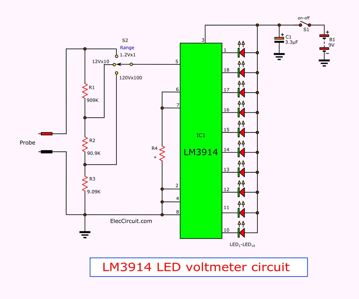
In case of display has the IC1-number is LM3914 meter display IC. In characteristics bar chart to the output pin 10 (pin 9 connected to the positive power supply Vcc to give the impression that the point of this project. By releasing it to float to pin 9 of IC). Pin 5 serves as input to measure the voltage into the IC. Then display a level 10 from 0.12V to 1.2V.
If the reference voltage is 1.2V if the voltage at pin 5 is equal or close to 0.36 Volt to LED3. If the voltage is 1.2V LED10 is lit, it is also shown that point. Full-scale voltage pin 5, so it will get from 0-1.2V voltage by R1, R2, R3 reduce the voltage to the probe handle itself. So that the voltage at pin 5 does not exceed 1.2V.
Each output pin can drive currents up to 30 mA and the current through each LED can be controlled by using a 1.2K ohm R4 here is the current flowing out of pin 7 is approximately equal to 1 mA. Ah, so the current through each LED is around 10 mA or about 10 times the current at pin 7, R4 is to control the brightness of the LED also makes reference voltage between Pin 7 and 8 at 1.2 volts.
When the time we had to take the ground of the circuit connected to the ground of the measures we are. According to the same the voltage.
Making and deployment.

In Figure 2, the PCB layout and positioning of components of this project.
When we press the switch S1 is ready to measure DC the voltage up. However, before Adjust the switch S2 to position X100 before. If we do not have to guess how much the voltage is measured. If no LED is attached to gradually move to the X10 or X1 S1, respectively. Do not forget the mouth of an alligator clip to the ground of the temple, which will air on the fire ground, it must be the same.
Readings.
By each LED to indicate that the first increment of 0.12V to 1.2V, so that each LED with a voltage equal to 0.12V when measuring the distance between the LED and the location where it is to be multiplied by that value. scroll to the S2 switch.
For example, S2 is at x10 and then measure the voltage at which the LED 4 LED 4 is 0.48, so the value will be multiplied by (0.48 x 10) = 4.8, we can estimate that The measured the voltage is 4.8V.
These values are approximate. The actual value may be less than 4.8V or more than 0.1V when the LED is lit for each of the two adjacent It shows that the voltage measured between the center of the LED voltmeter probe was used to measure the DC voltage rough. As the voltage at that instant. Usually, we measure the DC voltage in the range of 0-20V is mainly
Components list
0.25W Resistors, tolerance: 1%
R1: 909K
R2: 90.9K
R3: 9.09K
R4: 1.2K
Electrolytic capacitors
C1: 3.3uF 16V
S1: on-off switch
S2: 3 step selector switch
IC1: LM3914
Simple Digital voltmeter circuit »
Related Posts


I love electronics. I have been learning about them through creating simple electronic circuits or small projects. And now I am also having my children do the same. Nevertheless, I hope you found the experiences we shared on this site useful and fulfilling.
Clearly if the connectors add 100 milliohm and you have 2.6A then you get 260 milliVolt drop. IF 40 mV is max tolerable voltage then you can add infinite return backplane and still will be over spec by 260/40 ~= 6.5:1. You would need at least 6.5 parallel pin-pairs to reduce that connector only voltage to an allowable level and then have the rest of the circuit and the return path to deal with. IF the 50 milliohm value is in fact a typical average value then you have an almost intractable situation. If there are an equal number of connector at 50 miliohm in the return path then the problem simply becomes impossible.
sir this circuit 72volt how to make