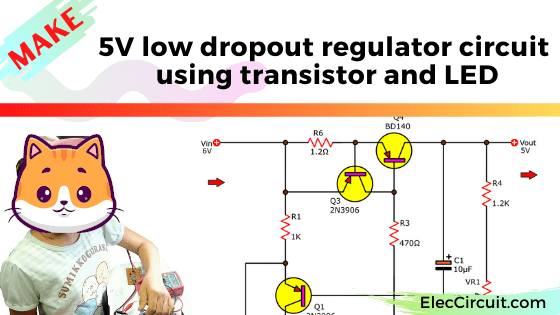
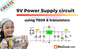
This is a fixed DC regulator, a 5V low dropout regulator type. It uses a transistor and LED as main parts. It requires an input voltage of at least 6V and there will be 1V lost inside the circuit. Therefore, the output voltage will always be 5V at 0.5A.
Why should we use a 5V Low Dropout Regulator?
Assuming that we need to use a digital circuit which is required a 5V regulated power supply. But we have a 6V battery that is incompatible with our intended uses.
I have many ideas but which is better?
- First, I will use a resistor to lower down voltage. But it also lower the current and become not constant.
- Second, I will connect a 1N5402 diode in series to reduce the voltage. In principle, it will reduce a voltage down about 0.7V, bringing the output voltage down to 5.3V, close to what we needed. But it does not work, because the output current got lower.
- Third, Use 7805 in a 5V regulator circuit. It can output a high current. But we cannot use 7805 because It requires an input voltage of more than 7.3V.
- Fourth, We need to use a high current circuit. Therefore, the 5V low dropout regulator is better in this case, or “LDO Regulator” in short.
The LDO Regulator can be created in many ways. Nowadays popular way is to use IC because of its convenience and high efficiency.
However, This circuit we are making consists of the transistor and LED. Because we want to make great use of old and common components in our inventory.
Read first for beginners: How do transistor circuits work
How does transistor LDO Regulator works
In a general, the regulator circuit has an input voltage that must be 3V higher than the output.
But this is a special circuit, 6V battery input is only 1V higher than the 5V output.
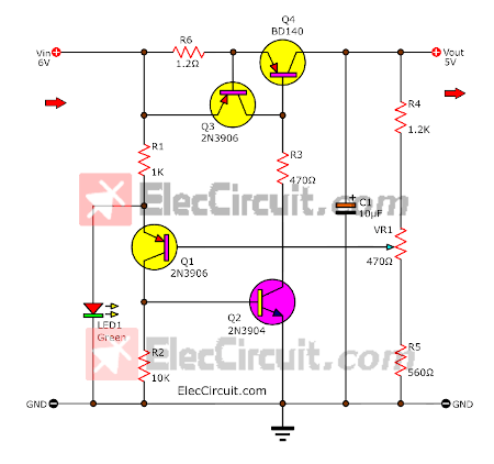
As the circuit above, the load connects the collector of the Q4 output transistor. This makes the transistor works in saturation, it causes a voltage drop across the collector and the emitter to be very low. Therefore, it can let more current passing through.
The current passing through depends on the type of transistors, in this case, is about 0.5A. And this transistor has a saturation voltage of 0.2V. Also, the voltage across R6 (current limiting resistor) is to be accounted for.
When the voltage across R6 reaches 0.7V, the Q3 transistor will get activated. At the same time, the output current is limited by R6.
There will also be some current flows through R1 to LED1, causing It to glow up. The LED1 has two functions, first is to indicate if the circuit working or not. The second is to keep a reference voltage that has been set at 1.9V, which is across the emitter of Q1 and ground.
The base current of Q1 is received from the output through the voltage divider circuit consisting of R4, VR1, and R5. The Q1 transistor conducts more or less depending on the difference between the reference voltage and the output voltage.
The result of the C-E of Q1 current makes the Q2 provide the current to control the base of the Q4 power transistor.
The capacitor C1 filters the output current to smooth up.
If we cannot find a transistor BD140. We may replace it with BD136, or BD138. However, these transistor has saturation voltage that is slightly higher than BD438.
For LED1 can be green or red to determine the reference voltage. Different color LEDs have different reference voltages. But we can always change an output voltage by adjusting VR1’s resistance.
The transistor Q4 is quite hot, therefore, it needs to mount a heatsink. We may use a TIP42 or MJE2955 instead (We can buy it later down the line) to increase the output current up to 2A.
Components list
Semiconductors:
- Q1, Q3: 2N3906, 45V 0.1A, PNP TO-92 Transistor
- Q2: 2N3904, 45V 0.1A, NPN TO-92 Transistor
- Q4: BD140, 80V 1.5A PNP Transistor,TO-225
- LED1: Green 3mm LEDs. Quantity: 1
0.25W metal/carbon film Resistors, tolerance: 5%, (Unless stated otherwise)
- R1: 1K
- R2: 10K
- R3: 470Ω
- R4: 1.2K
- R5: 560Ω
- R6: 1.2Ω 1W
Electrolytic Capacitors
- C1: 10µF 25V
Miscellaneous:
- Perforated board, Wires, Heatsink for Q2
Building and Testing the circuit
This circuit has a few components. Thus, we may assemble them on the perforated PCB. It may save some time to build.
We measure the voltage at various points as the circuit diagram below.
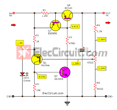
My daughter has tested it on a 10Ω resistor as a load. It can power a current of about 0.5A, and the output voltage reduces to 4.9V. It is close to when no load (5V).
This is the first LDO Regulator circuit, it uses a transistor as a key component. Next time, we will try making by using IC.
What is more? See More Power supply circuits
Download This
All full-size images and PDFs of this post are in this Ebook below. Please support me. 🙂
Related Posts

I love electronics. I have been learning about them through creating simple electronic circuits or small projects. And now I am also having my children do the same. Nevertheless, I hope you found the experiences we shared on this site useful and fulfilling.
Hi.
I need circuit low volt cut off. 12v battery when 10v than cut off.