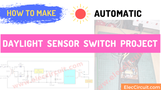
I am going to share an automatic daylight sensor switch Project. I like it. You may like it too. I want to control an Air pump (looked like this project), to works only daylight hours. To save electricity and help extend the use of the air pump.
Simple Light-activated relay circuit with PCB
So, I select a light switch controller Because there are fewer devices and easy build. Which is the circuit diagram below:
In today’s post, I’m going to share a simple light activated relay circuit. Why should you learn it?
Your daily life is busy. If you need to turn on the electrical device only during the day and then turn it off at night. Sometimes, You may forget it. It wastes time and wastes electricity bills too.
Is your life easier? If it opens and closes by itself. We are not a little wizard. Yes, We can do it by this circuit.
Read below you will get ideas.
You can use it in many ways such as the alarm circuits, light switch controller circuits, the strobe light photography controller, and more. It will control your electric load to be on-off with the light.
How light-activated relay circuit works
As I said, we will catch grasshoppers. It does not need to ride an elephant. Because It is too wasteful.
In this circuit, we choose it because it is simple and works well. That is enough for our necessity.
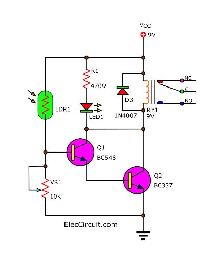
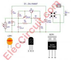
Let’s see in the circuit diagram. Both transistors Q1 BC547 and Q2 BC337 are connected together in the Darlington compound. So they have a higher gain.
When we shine a light on the photocell (LDR1). Its resistance will reduce. The current flows through it to the base of Q1. The Q1 gets enough bias current, so it conducts the higher current. They switch on, to turn on the relay, and LED1 grows.
R1 limits the current to LED1 with a safe value. D1 absorbs the current spikes to protects the external relay driver.
We can control the sensitivity of the circuit by adjusting VR1.
If we set its resistance is low, the sensitivity of the circuit is also low. But we set its resistance is high, is a high sensitivity, too.
Construction This circuit is easy. So you can assemble them on a perforated PC board. But you want to solder the components on the PCB below.
How to build
This project is easily suitable for a beginner. First, you get all the parts lists below.
Parts you will need
- R1: 100Ω, 0.25W Resistors, tolerance: 5%
- Q1: BC549, 45V 100mA NPN Transistor
- Q2: BC337, 45V 800mA NPN Transistor
- D1: 1N4001, 50V 1A Diodes
- LED1: any LED as you like
- LDR1: Photoresistor
- RY1: Relay with SPDT 10A min switch. Coil Voltage 12V. Coil resistance 150-600 Ohms
- PCB, wires and more.
For PCB, you can use a universal PCB. Because it is so faster. However, you can make a normal PCB as the layout below.
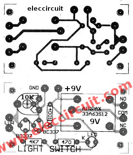
PCB layouts and Components layout of Light Relay Switch circuit
Testing
First of all, Check and check the circuit again. Second, try to enter a power supply source in the circuit. Then, adjust the VR1 to sensitivity by you want. Last, shines a flashlight on the photocell. You will hear the relay pulls in. It works.
Automatic daylight sensor switch Project
Then, we apply the above circuit to make the automatic Air pump. We should make a 9 volts DC power supply and connects them together as Figure 2
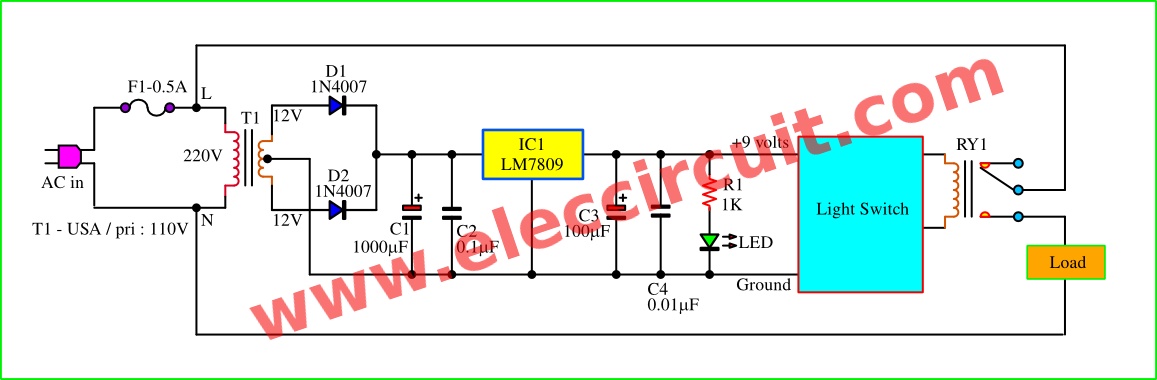
Figure 2 Block diagram and 9 volts DC regulation of daylight sensor switch circuit.
Since we have 12V CT 12V or 24VCT transformer so set this circuit form. Which is DC voltage regulator using LM7805 link this circuit : We assemble all components on Perforated board as Figure 3, Cut a hole for installation AC outlet, as Figure 4. and install another part in the box(LDR, both LEDs, AC line, and more) and connecting all wiring as Figure 5. Then test this project watch in the video below and then Installed this project For practical purposes as Figure 6, to adjusts the LDR to the light way.
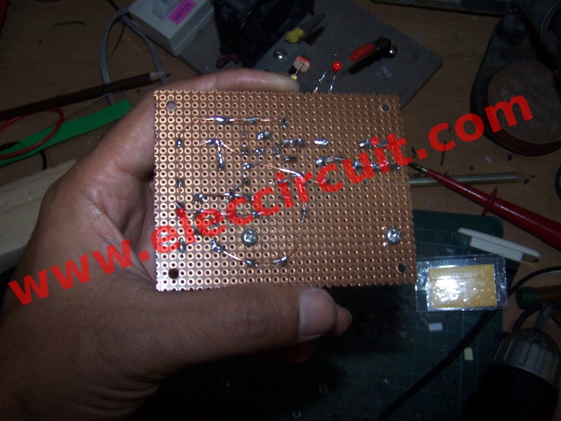
The bottoms layout to assemble all components on the Perforated board.
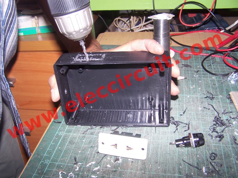
Installation AC outlet.
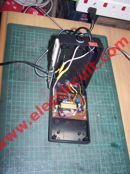
Connecting all wiring
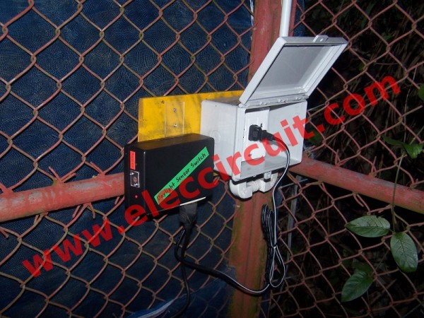
Figure 6 Installation project For practical purposes
Testing this project
Apply AC power to this circuit and take lamp. then shade the photoresistor or does not shine any lights on the photoresistor. We will hear relay pulls in and the lamp glow now.
My son apply this project to control his an artificial waterfall.
Because It is being used near water, we use this is And, Then He tests this daylight switches. Using hand, blocking the light at the LDR Sensor. The pump in the artificial waterfall working so well.

Related Posts

I love electronics. I have been learning about them through creating simple electronic circuits or small projects. And now I am also having my children do the same. Nevertheless, I hope you found the experiences we shared on this site useful and fulfilling.
To think, I was cofsenud a minute ago.
Hi Addriene,
Thanks for your feedback.
maybe u send me the basic proposal of this project? i’m really need it.
can i have the proposal for this project ?
can you list the component
Can you order the basic components somewhere or do you sell a kit?