How do quickly learn transistor and LDR circuits? In this post, I am going to show you how to learn quickly. My children want to create a simple automatic night light circuit. It is special. Why? It will be light in the dark. This circuit uses 5 parts only and is cheap.
UPDATE: Now my daughter is growing up. She is ready to learn these. Most recently, she made a Simple Automatic night light circuit.
What you should know first:
Lego Automatic LED Night Light circuit
Many children enjoy Lego every day. My children, too. They will build the Lighthouse tower with LEGO blocks.
Sure, it is not important for you. But…
I hope you improve your understanding of electronic circuit working. For example, the voltage divider circuit, LDR, resistors, transistor works, and more.
Ready to get started?
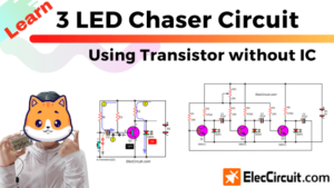
How circuit works
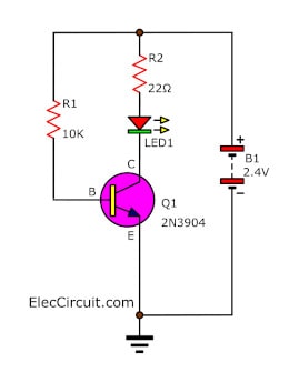
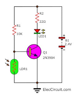
See in the above circuit, the simple transistor driver for flashing LED.
Supplies detail:
- LED1: Multicolor Flashing LED, 3mm
- Q1: 2N3904 NPN transistor
- R1: 10K, 0.25W resistor
- R2: 22Ω, 0.25W resistor
- 1 two Battery Holder
- B1: 2 NiHM(nickel-metal hydride) AA batteries
See other more simple electronic circuits
How to build
Assembles them on a small breadboard. Then, apply the 2.4V power supply ( 2 x 1.2 V battery) to the circuit.
Assemble the circuit on a breadboard
A small current flows through to R-10K to the base of transistor Q1- 2N3904. It makes a large current flow through the collector to emitter lead, and LED1 will glow up.
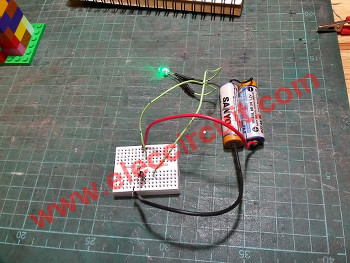
LED glow up
Recommended: Learn Electronics with easy steps!
Next, put LDR into the circuit.
Lego automatic LED flasher light circuit
When the light to LDR, its resistance is low. So the R1’s current flows through to LDR instead. It makes no current to the base of the transistor so it does not work. Thus, LED will go out.
After, turns off the light. The resistance of LDR is high up, so the R1’s current can flow through the base of the transistor again.
It makes a large current from the collector flow to the emitter. Thus, LED glow up or flashing light.
In the video below he builds and makes them!
Not only that we will learn more by making this project below.
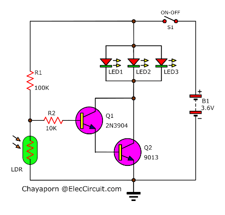
Kids Automatic Night Light Circuit
Imagine, in a dark bedroom, we will get up and go to the bathroom. We cannot see anything, even the doorknob. Is it good? Little light enough to see the way or the doorknob.
Yes, It is a good idea.
See the circuit, It is similar to the circuit above.
We add components from the previous circuit just a little.
Design circuit concept
Selecting or positioning equipment, or testing the circuit until it works well is important. It spends a long time to get good results. But you are easier when finished reading this article. I’m glad to save you time.
How bright should a night light be?
Of course, if the light is less, there will be no benefit. But if too bright, it also affects sleep.
What light color is good for sleeping?
Or, Does Some Color help You Sleep Better?
Some information says that the light red color helps us sleep better. But it also depends on the person.
For us, choose a soft white light, and 3 White LEDs because they can see clearly and do not disturb the eyes too much.
Should use a battery?
We intend to run this circuit from a battery. Because it is safe for all.
But we should calculate the likely battery life.
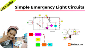
I will use 3 LEDs in parallel. They need a current of 20mA to 60mA. And the voltage is 3.3V to 3.6V for a common white LED.
Thus, we choose 3.6V NiMH Batteries (3 x 1.2V AA cells in series).
Battery life:
If we use a current of 20mA for 10 hours per night, we use about 200mA each day.
If the battery is 2000mAh, we can use it for about 10 days. (2000mA/200mA) per charge.
Is it Okay? Perhaps, longer because of the low current.
What is next?
See in the circuit, I put another one of the transistors (Q2). Why?
From testing with only one transistor. LED does not bright when dark.
How to builds
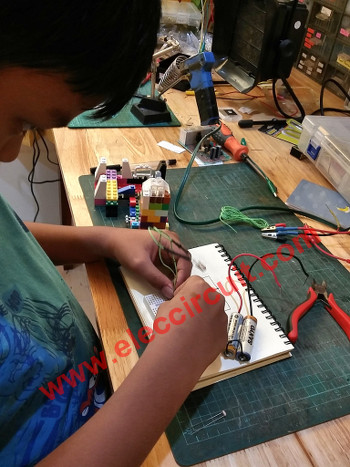
My daughter prefers soldering the circuit to using the breadboard. I started teaching her how to solder copper wires, and connect devices without using the PCB first. it’s easy and fun.
Flip the board over and bend the wires from the components to anchor them to the board. Then, solder them as the circuit layout.
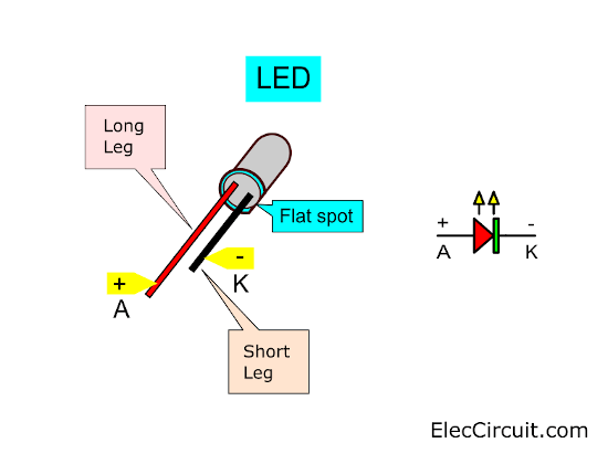
Put devices in proper polarity
You need to put these devices in the right polarity. Otherwise, they do not operate as they should be.
LED:
Must connect a correct polarity only. The LED will light up. But it is the wrong polarity (Reverse bias), it will be no current flow.
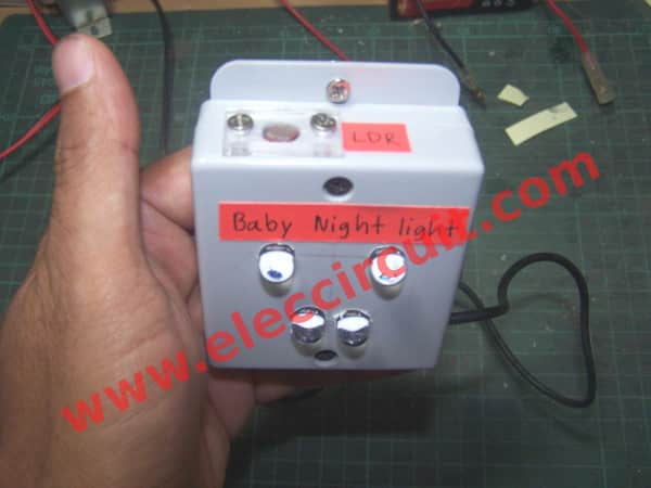
Baby Night Light Circuit
My daughter was about 1 year old ago. It is normal to wake request milk several times each night. If turn on lighting up. It causes inconvenience and is uneconomical.
We are thinking to buy a baby night light instead of a normal lamp. It is lower light to reduce visual distractions. But it is enough to see the bottle and be able to breastfeed.
This method makes it more power-efficient than turning on the lamp for the night. Because I turn on use power of 20 watts, but this system consumes just 1 watt only.
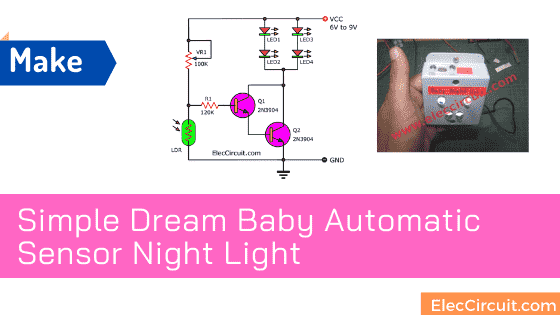
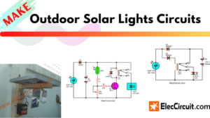
I design simple dream baby automatic sensor night light as Figure 1. Since it is cheap and easy to makes.
This ideas circuit
I see in amazon look at many baby night light and I like auto light ideas because it is convenient. It does not need to have switch on-off. The LEDs glow brightly just when in night or dark only.
How does it work
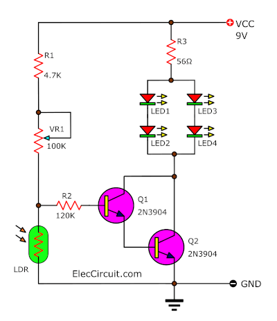
Figure 1 is the circuit diagram that I use 4 LED super bright as nigh light so saving. And use an old small DC adapter 9volts is a power supply that has high performance than a transformerless power supply.
I use a photoresistor(LDR1) as a light sensor its resistance of it will change with the light.
The current flow through to VR1-potentiometer and LDR1 is set circuit in divider form.
Learn how voltage dividers work
Normally the light strikes the photoresistor. It causes a voltage drop across it is low voltage. So not have a current flow to the base of Q1.
Therefore Q1 and Q2 do not work. So the LED goes out.
Then, not light to LDR, cause voltage across them is high. It causes have a current flow to R1-120K to the base of Q1, and Q2. So, they have connected as Darlington compound so high gain ratio.
How transistor works on Darlington
Thus the current through to LED1, LED2 to collector and emitter of Q2 to ground. The LED1, LED2 is glowing now.
How to build its
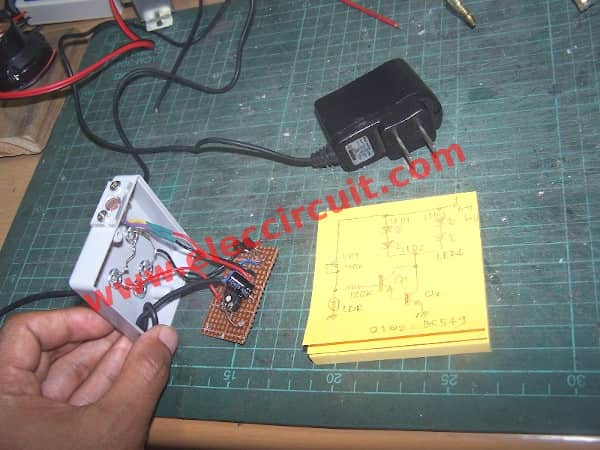
This is a very simple project. I assemble parts and wiring on the perforated board or Universal PCB board. And install them into the universal box As Figure 2.
Read Also:
- Learn ON-OFF Light and Temperature Controller using 741
- Making a Simple Light-activated relay circuit with PCB
- Sound Activated Switch Circuit with PCB
Next, I test it in a bedroom. We can adjust the sensitivity of the circuit with VR1.
Lastly, I take it to really use it as the video below.
Note:
1. This circuit does not use R-limiting current because we use LED super bright that uses voltage 3-4V in fully light.
And This supply voltage is 8.4 volts approximately.
2. If you use an AC adapter that not a good filter, I always insert a 100uF 25V electrolytic capacitor across +V and Ground to smooth noise or ac ripple voltage. But it does not need it. If you use a normal DC power supply regulator.
Check out these related circuits, too:
- Automatic Night LED light switch circuit using solar
- How to make automatic daylight sensor switch Project
- Simple light controller circuit using CD40106
Related Posts

I love electronics. I have been learning about them through creating simple electronic circuits or small projects. And now I am also having my children do the same. Nevertheless, I hope you found the experiences we shared on this site useful and fulfilling.
Awesome Circuit!!!!!!!!!!!
Hi MR OHM 1970,
Thanks to my friend.
KVL And KCL circuit
no resistor in line with each led?
a no go!
Hello, Reiner,
Thanks for your visit. Yes, we should add a resistor to limit current for LED.