If you like the transistor amplifier. You may also like a VU meter using the transistor. They are one type of LED VU meter circuits.
Also, It works with an integrated amplifier circuit. To show a level of the sound signal or rhythm of the music by the LED flash lighting.
Are you a beginner? Learn Basic Electronics
Why should use transistors version
You may have a question. Is it better than IC? I cannot tell you. It is the best VU meter. But I can show you the transistor is so great all the time.
- Easy to get them—Although they are quite ancient. But it is still always popular.
For example:
2SC458 transistor, now The factory quit producing it. But we can use other transistors instead like 2SC828, 2SC945, 2SC1815, etc. - Cheap—They are inexpensive when compare with IC. Although we need to use a lot of transistors. If it breaks out. You can fix it one by one, do not change it all.
It is different from the IC. You need to change IC only. - Simple circuit—suitable for learning basic electronics
Recommended: Learn transistor circuit works here
5 LED VU Meter Circuit
Look at the circuit. Here is a simple VU meter. It has only the necessary parts.
When entering the power supply to the circuit. Then, connects an input of the VU meter to the output of the amplifier.
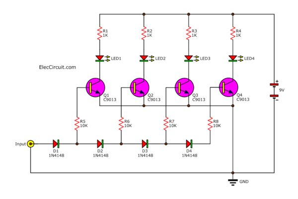
Next, four diodes D1, D2, D3, and D4 pass the input audio signal. They have 2 functions.
- First, rectify the audio signal, AC voltage to DC voltage.
- Second, divide the audio signal to gradually decrease, respectively.
To forward to each the transistors Q1-Q4 through Resistors, R5-R8. They limited bias current to the base of Q1-Q4 to increase current up to each collector.
To drive LED1-LED4, to show the level of the signal. The LED1 displays an audio level with the least light. And the LED4 shows the most level signals.
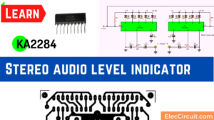
Related: KA2284 Stereo audio level indicator
I think you may not understand I said. Back…reading.
Each diode has a voltage across is 0.6V. Suppose the signal is 1.8V.
It causes the current can flow to three diodes, D1, D2, D3, So, LED1-LED3 glow up. But LED4 and LED5 will go out.
Note: likewise you can see the second circuit that using more LEDs, too.
Recycling free white SMD LED from e-waste
25 LEDs VU meter Circuit (Increase LED)
The weakness of the previous circuit is cannot display low voltage. So, we need to improve it.
In the circuit below. It has a voltage doubler circuit, C1, C2, R1, R2.
They approximately double an incoming AC voltage. Also, the output is DC voltage.
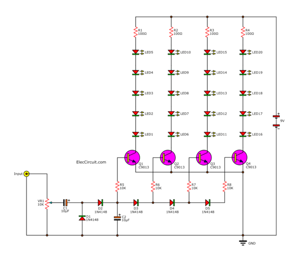
Adding LEDs for 25 LEDs Analog VU Meter circuit using transistors
Make the audio signal into more voltage. So, all transistors can drive all LEDs to emit light much more.
Recommended: Learning Electronics for beginners!
How it works
First of all, when applying the power supply to the circuit. And VR1 passed the input signal and adjust the sound more or less.
Then, flows through the C1 signal coupling.
Next, the signal goes into the circuit to increase the voltage with D1 and D2. Which both diodes rectifier AC to DC with positive and negative together.
After that, DC voltage comes to C2 to filters into a smooth DC voltage.
The first part of the signal will flow through R1 to the base of Q1. It works to drive LED1-LED5 to light up.
The remaining signal is sent through diodes D3, D4 and D5. This will serve to break the sound signal to gradually decrease, respectively.
To forward to the transistors Q2-Q4, each level of the signal strength coming.
Then expand to the LED current to light the rhythm music.
Here are a few related posts you might want to read:
- Digital multimeter circuit using ICL7107
- Analog VU meter schematics
- Simple Moisture Meter using 2N2222
Not only that see improved circuits with PCB layout.
20 to 40 LED VU meter schematic
This is 20 LED VU meter schematic is designed for who want to have a circuit that can drive LED up to 20 pcs (Stereo 40 LEDs). Which the circuit using a generally IC will cannot directly connect to uses.
In addition to this project is very easily circuit and also can modify to drives Solid State Relay for easily control a larger lamp.
As you see the complete circuit of the projects in Figure 1.
The working of this circuit
An input signal from the power amplifier is passed through to VR1, to adjust the amplitude of this input signal at the proper level.
Then, the signal is sent to the voltage doubler rectifier circuit. That consists of C1, C2, D1, D2 to the circuit. And all transistors Q1-Q10 that together into the voltage compare circuit.
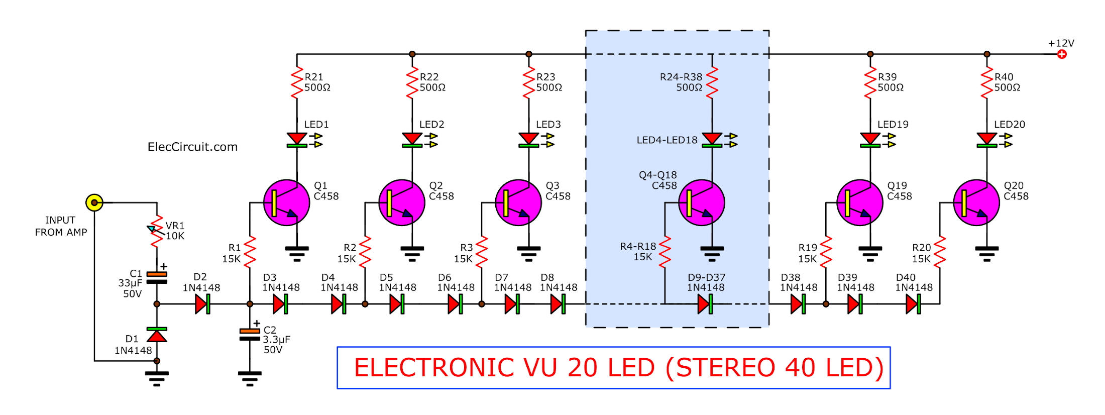
20 (40) LED VU meter using transistor circuit
We can see the bass circuits of each transistor will be set a bias with D3-D40. To provide to have a voltage bias is different for every 2 volts, respectively.
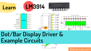
Recommended: LM3914 VU Meter circuit
So, transistor Q1 will start work at a lower signal and Q20 will work on the strongest signal.
The section of the circuit is in the dash as the shortening of the circuit is repeated. They consisting of Q4-Q18.
Download This
All full-size images of this post are in this Ebook: Elec Circuit vol. 2 below. Please support me. 🙂
How to build
We Assembly the circuit onto the PCB layout as Figure 2 correctly.
So, must be extra careful is. Devices with terminals such as Diode, Electrolytic capacitors, and LED will are connected right terminals only.
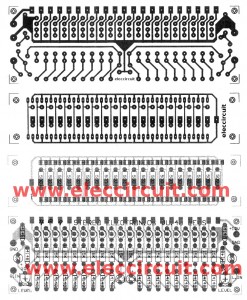
Figure 2 the PCB layout and the components layout of the 20 LED cheap electronic VU-meter using transistor project
When the assembly is completed. Then, test to provide the voltage power supply to this project. While connects the input signal from a speaker of a power amplifier.
Next, turn on it at the highest audio. Then adjust VR1 to LED glow fully all LED. Now already have fun.
The components List
Q1-Q20: 2SC458, 2SC828,C945,C1815, 45V 0.1A, NPN Transistor
D1-D40: 1N4148, 75V 0.15A Diodes
R1-R20: 15K, Resistors 0.25W +/- 5%
VR1: 10K, potentiometer POT
C1: 33uF 50V, Electrolytic
C2: 3.3uF 50V, Electrolytic
L1-L20: LED 2 x 5 mm.
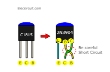
Note:
For friends who cannot buy C458 or C1815 transistor. You can use 2N3904 instead. But you need to swap the legs and turn them back. Be careful with pins B-C short-circuited. You may be able to use insulator on pin B.
See others below.
Great 20 LED VU meter schematic
The complete circuit for VU-meter.
Note: This circuit worked well as Video below:
Check out these related circuits, too:
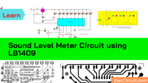
- Sound level meter circuit using LB1409
- Stereo Balance Indicator Circuit
- L1424 Peak Hold VU meter circuit

Related Posts

I love electronics. I have been learning about them through creating simple electronic circuits or small projects. And now I am also having my children do the same. Nevertheless, I hope you found the experiences we shared on this site useful and fulfilling.
I am finding a circuit to built my own timing light to adjust my engine timing, but i didn’t see such circuit in this. To everybody who knows how to built the timing light circuit, please send me one..
Hi man, if I use a microphone at Input will it work fine?
Pls can u develop a fm transmitter for cell phone(nokia c3.00) and send it to my email to download or do u has any suit for that pls let me know thanks.
Hi John Akam
I am not sure can help you made done project.
Please look at: https://www.eleccircuit.com/tag/house-fm-transmitter/
https://www.eleccircuit.com/fm-wireless-transmitter-circuit/ with PCB layout
Grazie per il vostro articolo esplicativo e per l’entusiasmante ora di elettronica che si prospetta per il prossimo futuro.
The English is perfect..Thank You for yet another GREAT PROJECT!!!!
Hi sir, good evening.
The project is simple and easy to do.
Thank you and tomorrow I’ll try to make it and use it for an electronic load control for coupling two inverters.
The firts is 48v DC to 220V pure sine wave stand alone about 300VA.
The second is grid connected to the first and works from 400v 1000W peak of solar panels .
When the sun is strong the energy breaks the first inverter and I need to put this energy gradually into a battery charger.
I’ll send you more comments.
Thank you
Gostei do circuito de vu vc podes mandar -me o layout do amplificador 22000wa
tts
I am sorry. I do not have 22000 watts amplifier circuit.
To jsou Paradni schemata ! Diky za ne ! To u nas tezko shanim,ale,tady najdu hodne paradnich schemat i plosne spoje ! Je to SUPER ! Dekuji ze mi to posilas ! Jirka – Czech Republic – Europe
Hello Podekovani!
Thanks for your visit. I am happy that you like this circuit.
Yes, You may use the universal PCB, too.
Thanks again,
Apichet
Muito bom o artigo..
Hello Zelino,
Thanks for your feedback. Happy New Year.
Have a great day.
Thanks
Apichet