This is a switch mode LED driver circuit. When it is applied to the battery. How to make it light a long time?
We can use battery longer than usual. This is an issue that we need.
When it is saving, If applied to the other supply, would make saving for sure.
Simple Switch mode LED display circuit
Figure 1 as application circuit by the source is a voltage of 9 volts that we must provide high power. To efficiency and a long lifetime. The transistors T1-acts as a switch is replaced by S in figure 1 by having others components are D1 and L1 as working devices of the original theoretical.
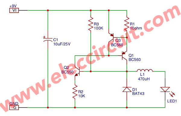
Figure 1 DC converters for drive LED
The start working. From the flow of current through R3 to pin base of transistor T2(BC550). (Now LED D2 is no light. Although there the current already flowing through R3. Because, LED light up. The voltage is higher than 0.7 volts.) At started this, it was such a transistor bias resistance of T2 reduced. Access conditions applied.
It causes T2 connects the base of T1 goes to a negative voltage by through conduction of pin collector-emitter of T2. Resulting flow current of power supply +9V volts via R1 into pin emitter out away pin base of T1(BC560) go to T2 complete
Now T1 has a bias so provided current out to pin collector, current from source +9 volts, to provide current to coil L1. By this method, As a result, the voltage drop across the coil to accumulate in the form of the stall are current will flow even more, according to the buck converter.
The current of the coil is current only to flow through R1. When much more current flows, the voltage across R1 of 0.7 volts. (current about 70 mA) Transistor T3 conditions into conduction. because the voltage that across R1 is attached to the pin bias T3 (BC560).
(Peripheral as bias between pin emitter and pin base, if emitter-base voltage has value 0.6-0.7 volts will make transistor such conduct. Or into the conduction state.) T3(BC560). So conduct from pin emitter send to collector pin.
Results conduct a positive from the power supply +9 volts affects the bias pin base of T1. Which is resulting in transistor PNP T1 stop conduct current.
Or another way to say that when T3 conduct is equal to a two-way current flow are way one through R1, another through T3. So makes the voltage at pin base of T1 has value as positive more, the bias of circuit T1 low down T1 stop conduct current.
If you look back at the pace of work in the beginning. The transistor T2 is the default device conduction. The performance of such transistor, making T1 conduct follow-up. Results conduct a current of T1, then In addition supply to L1, Also lot of bias to the pin base of T2, the current results add to the current T1 increase follow.
The current in coil increased, respectively. Called Adding this that. increase the proportion Or Linear When a high current, until T3 work. T1 will conduct the magnetic field in L1 and collect the collapse. To the current through the LED-D2 through diode D1.
Now transistor T2 is received reverse bias. When measured at the pin base of T2 relative to ground potential negative voltage. Or called the voltage drop across L1 is negative (because is Point to same pin base of T2.) If you go back to the basic circuit shown in
Figure 1. The write points out that P is the same bias pin base of T2. Or, we measure the voltage of the coil L1 at this voltage, the point P must be reduced.
The L1 provides current to LED until exhausted (to value zero). Thus transistor T2 will again begin to conduct current. Because if L1 still run, Also has a reverse bias to T2. This work will be cherished throughout time. Continue to supply the LED, the device D2 in the circuit.
Transistor T1, T2 is connected same as a thyristor tetrode. Positive feedback to frequency oscillator generators, the transistor T3 makes this system works Certainly more. Or as ensure set current turn off to the transistor T1.
Figure 2. The prototype circuit to drive current LED
In implementation. Because of such circuits. There are a few parts. The circuit can be assembled into a Universal PCB Board as Figure 2 or PCB design is achieved depending on the convenience.
Based on the LED driver circuit when a load more current. One problem is that this circuit cannot oscillate. Because a Load is used high current. Similarly, a resistor with low resistance. The output voltage so low as well. The T2 cannot run continuously.
We can fix the problem by increasing the capacitor value of 0.1 microfarads. To the point P of the primary circuit. In the above article. Or The capacitor such to drop across on the pin base-emitter of T2 will fix this problem.
To optimize the Supply Current of the circuit. Should put a capacitance of 10 microfarads (electrolytic type) cross into at point the output voltage. Because of the circuit such as the rectifier circuit with no voltage smoothing filters.
You will use these principles of the circuit, to other applications. Better than the LED driver circuit only.
Recommended: 1.5V 4 LEDs Flasher circuit using transistors
Not only that If your needing is used for longer LED displays to show the status of the battery.
Try!
Battery status monitor circuit using IC-7555

Simple battery status monitor circuit using IC-7555 or low power LED flasher by ICM7555
Normally, when you need to use LED display status of the battery 6V-12V. Just add a resistor in series only. It is easy and saving.
But not cool and consumes more power.
– The impression of a bright that continuously. I think that did not noticeable it.
– When the LED light as well So consumes too much energy. Although the LED need voltage is 1.8V only, but it uses too current is 15mA-20mA.
A wise choice
– The LED flashes very prominent.
– Find out how to use the current less than 1mA. When several ten years ago. I’ve used a LM3909 of LED Flasher/Oscillator IC. (View circuits that using this IC number.) It is built for a particular flashing light or low current led flasher so easy to make and includes a very small amount. But unfortunately. Now IC manufacturers stopped producing it.
But we also have the option of interest, may be better than. If you are familiar with the IC 555 is a relative of the family is ICM7555 (or 7555IPA) with the same features. However very low power consumption. Because the internal structure of CMOS, So works great.
You take a look that the circuit is easy like I said or not. As shown below. You see not wrong, it using only three pieces, it can make the LED to flashes. By pull current from the power supply is only 0.15mA. It is designed as a typical Stable multivibrators circuit. (If you do not understand see this web. We have several circuits)
Special! In a normal circuit, the capacitor will discharge directly to ground. However, for this circuit, the capacitor is discharged through LED1, so that LED1 flashes intermittently.
Just this you have a simple battery monitor circuit by IPM7555 Some people would say that’s not worth it. This circuit is more expensive than the old method. However it can extend battery life by several times, or Adapted for low current power supply such as solar or other alternative energy sources. They result is the same.
This circuit worked you can builds easy as video below:
Keep reading: ‘ High power LED flashlight circuit’ »

Related Posts
I love electronic circuit. I will collect a lot circuit electronic for teach my son and are useful for everyone.