Imagine you want to go on a forest without normal AC power main. But sometimes you want to use a TV or laptop or electronic maintenance work. A suitable alternative is to use this 200W inverter circuit.
First, I recommend Simple working principle of the inverter. If you have understood well. Now, we will learn the operation of the 200-watt inverter diagram, continuously.
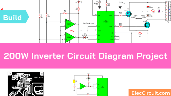
This circuit is quite simple because we use ICs and MOSFETs. But we have details that need to be learned.
Simple inverter block diagram
In the block diagram below, Starting from the frequency generator circuit or the oscillator.
They work with IC2-SG3526. It is a pulse width modulation as the next figure. It shows the internal structure.
And, It will produce the rectangular signal on the output frequency of 50Hz to both Output A and B.
Which both these output signals have a phase difference of 180 degrees all the time.


That is if a status of the output A is high. But the Output B will be low.
Or,
If Output A is Low, Output B will be High instead. These two signals are sent to control the output transistors Q1 and Q2
Both transistors Q1 and Q2 are Enhancement MOSFET type of N channel. So, They do not conduct current simultaneously. It causes the current that flows in the primary coil of transformer T1 flow switches at all time.
The Electromagnetic field so swelled and collapsed, inductor to the secondary. It gives the voltage AC 220 volts at a frequency of 50Hz to the output.
Temperature Protection of 200W inverter
After the circuit work will cause heat up the transistor. The power output (Q1 and Q2), if they are too hot. They may be dangerous to the transistor.
Especially when it requires more power to the load. So we need to check the temperature of the heat sink. Are overheat for Both transistors?
The device this functions is PTC (Positive Temperature Control). If the temperature rises abnormally, the PTC will send the result to IC1, op-amp IC. Then, it will reset the command to IC2.
So, IC2 stops the frequency generator. The end result is that both output transistors stop, too. To prevent damage to the transistor.
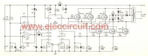
How 200w inverter circuit works
Then, we see circuit real use, as shown below. Which has the working principle of the circuit is divided into 3 sections, oscillator, output, and protection.
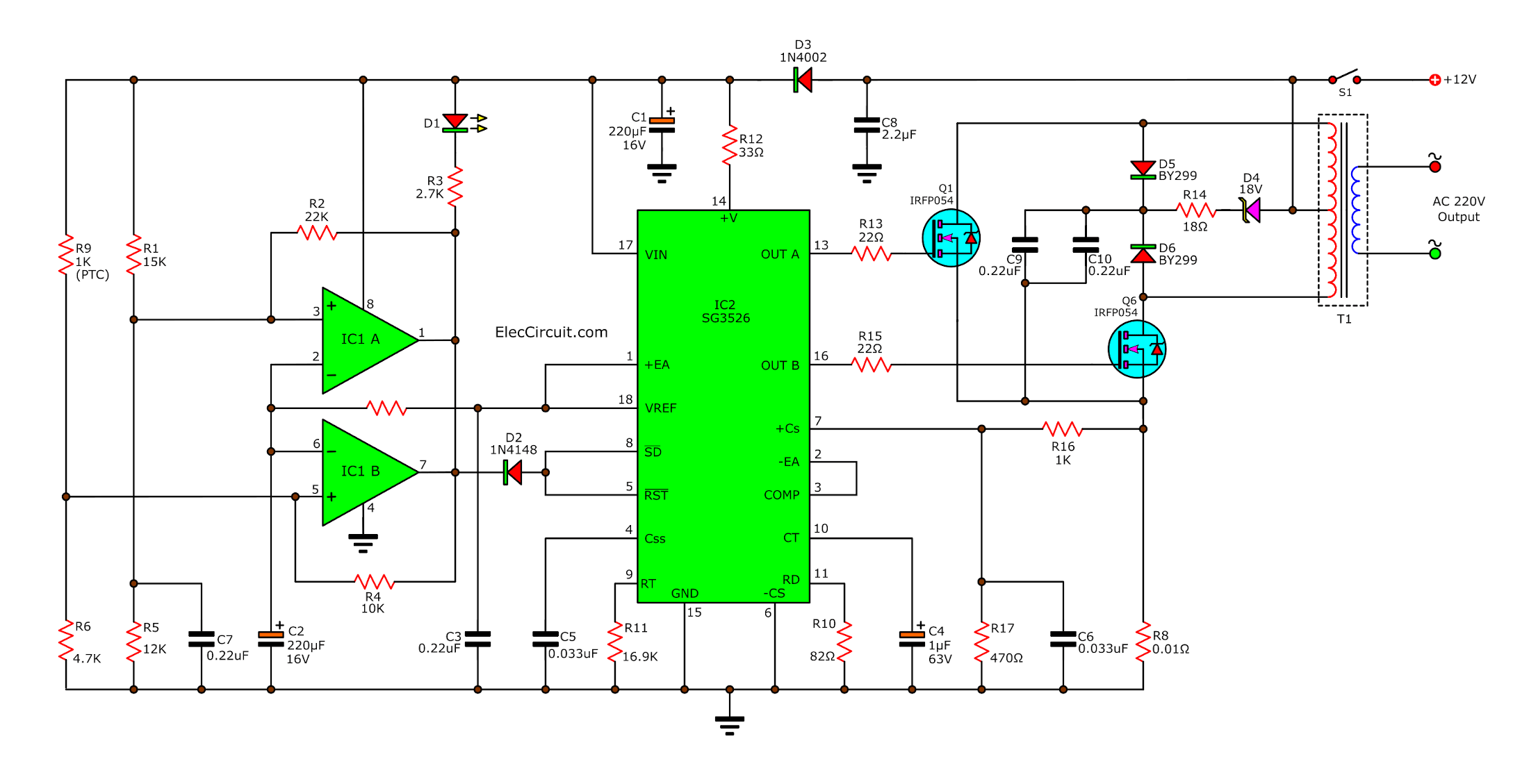
Starting when push switch-S1. Which is a switch turn-on. The voltage +12V will be sent to diode-D3 provided the IC2 at pin 14, pass through resistor-R12 of 33 ohms. There are C1 as decoupling backup current to IC2.
Keep constant voltage for IC
See in the circuit. We bring a positive voltage(the supply voltage of IC2) via the diode-D3 before. Because we want to make IC2 get the constant supply voltage at all time.
Next, see the source voltage of the battery will be sent to the output circuit directly.
The function of output is the characteristics of switching. To begin, the switch is in the range state-on. It may cause the supply voltage source dropdown.
Which this drop voltage will cause IC2 malfunction. We should put the D3 block between the voltage source and supply voltage of the IC
When the source tumbled. Because the output starts the conduct current. But voltage at the anode (A) of D3 lower than cathode (K). And it has the voltage across of state Reverse bias.
They can not conduct current. Makes the output circuit can not draw on the accumulated charge of C1 is correct.
As a result, the supply voltage of IC2 not tumbled like a voltage source.
Reverse voltage protection
Besides, D3 protects the damage of IC2 (oscillator circuit) from the connection wires from the wrong battery terminals. If the wires alternating positive to negative and negative to positive.
The D3 conditions in Reverse bias status. It does not conduct current. The Circuit will stop working without damage.
Setting Oscillator section
When there is a supply voltage, so IC2 starts to produce a frequency. This frequency is determined value of R11 and C4 that connected to pin 9 (RT) and 10 (CT) respectively.
This frequency is 50Hz of AC main power in a rectangular waveform signal. At, the output pin 13 (OUT A) and pin 16 (OUT B).
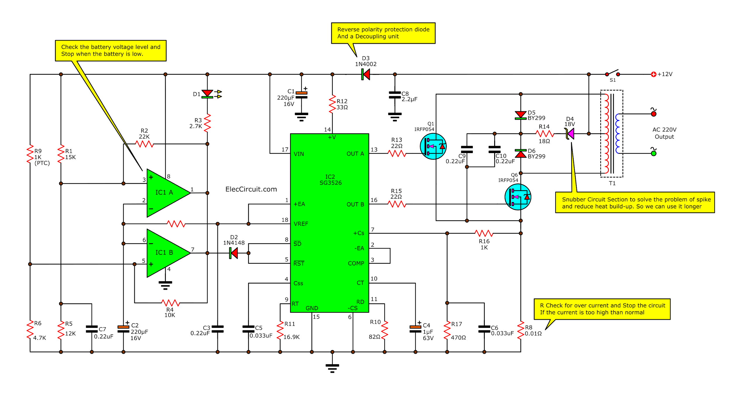
The output power MOSFET
As figure below, when IC2 generates a square wave frequency of 50Hz at output pin 13 and pin 16. Both signals have a phase difference of 180 degrees. Then, it will send to R13 and R15, to bias the pin gate of both transistors Q1 and Q2, IRFP054. They are MOSFET type N channel, within diode damper Diodes.
Both MOSFETs alternately conduct current. If anyone has a bias. a signal at the gate, it will conduct current(ON). But if it gets a low signal, it will stop conduct current(OFF).
Then, the current to flow in primary coil of transformer T1 into (D) drain out to the (S) source of Q1 and Q2. And full circuit at ground by pass to R8 value 0.01 ohms.
Which this resistor will check the amount of current in the output circuit. We will learn next.
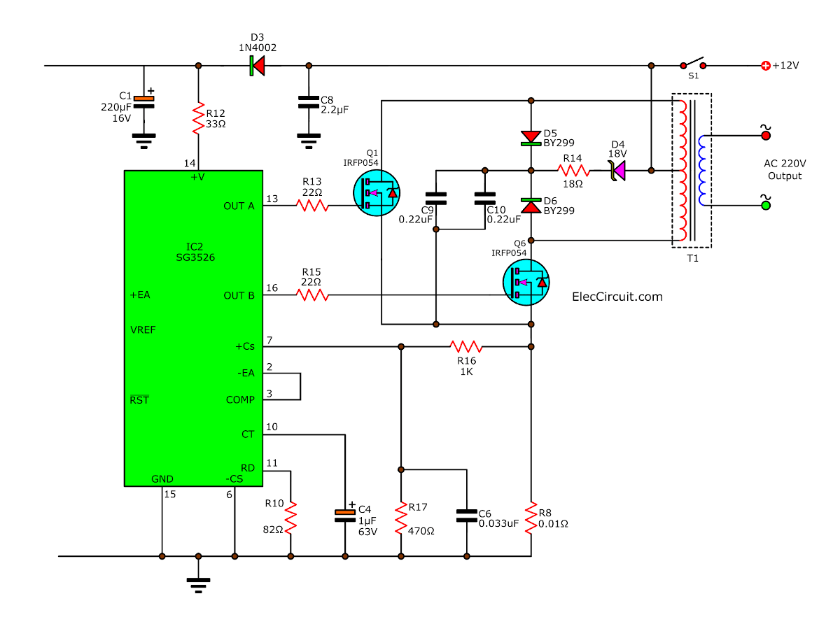
Snubber circuit clean spike voltage
Both MOSFET (Q1 and Q2) work look like the switches. It has a spike voltage at the drain. Which happened while changing the state, ON to OFF. This spike voltage is very higher than the supply voltage many times.
Which is extremely dangerous to the power output transistors. So, it is necessary to eliminate this spike voltage out. We called this a snubber circuit.
The snubber circuit consists of D4, D5 (BY299), D6, R14, C9 and C10. For D5 and D6 are diode works faster or called Fast Revovery Diode, BY299.
Under normal conditions, D5 and D6 will do not conduct current. Which it will conduct current when the voltage at pin drain of Q1 or Q2 rise. Until having a value greater power supply (+12 volts).
The current will flow through both diodes into charge to C9 and C10. And, if the voltage at D (drain) of Q1(IRFP054) and Q2(IRFP054) is higher than 18 volts. It will make the 18V Zener diode, D4 conduct current through R14 (18 ohms).
Which operation of all the equipment as a result to lower the spike voltage. Likely that both power transistors will be damaged less.
Protection of the Inverter
We see the protection circuit. Which is divided into 3 sections:
- Overload output current protection
- Output overheat temperature protection
- Battery Checker
If there is malfunction occurs. The protection will stop
the operation of IC2. The frequency generator stops the output transistors. To protect against damage that may occur.
In addition, also a battery checker to the power supply voltage to the inverter circuit. All checks will stop the circuit, indicate by D1(LED).
Overload output current protection
This has a R8 as main in working. It is very low resistance, 0.01 ohms. It works with pin 7 of IC2 (pin + CS).
Normally, the voltage at pin 7 is very less value(nearly 0 volts). But the voltage at pin 7 is positive up, makes frequency generator-IC2 to stop, and stop the operation of the output circuit.
The current alway flow in both output transistors with full circuit through R8 first. In normal conditions, the voltage across R8 is very little (millivolts) or may call empty.
The voltage drop across the R8 is divided into two parts, with R16 and R17. In R17 will send directly to pin 7 of IC2.
When the source voltage (across R8) no voltage, and pin 7 of IC2, too. Makes IC2 can generate the frequency to bias Q1 and Q2 as normal.
But when the current flows in the output circuit too much, and the R8, too. Also, the voltage drop across so increasing. As a result, pin 7 of IC2 have positive voltage is increased by positive volts, and IC2 stops.
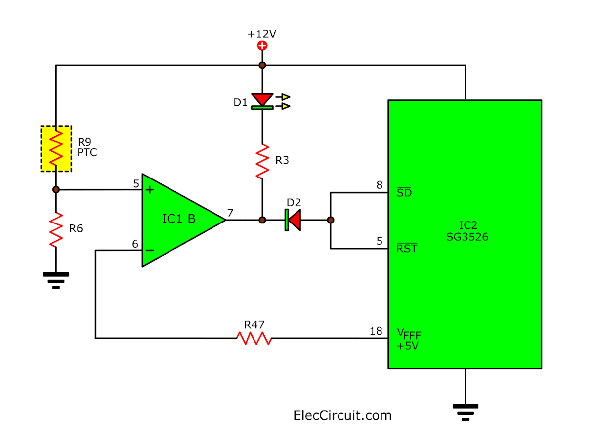
Output overheat temperature protection
There is important to check the heat in the output transistors. Is too high? If found too high heat, it will stop the operation of the oscillator circuit and the output circuit, too.
See in figure below, this device monitors the temperature is R9. Which a resistor that changes value with temperature. The R9 can be attached to the heat sink of the output transistors. Which is resulted in a lot of heat disorders. R9 resistance will increase.
The IC1B (op-amp) serves comparator circuit. There are the reference regulator circuits +5V at pin 2. It is the inverting pin. This voltage comes from pin 18 of IC2.
If we back to see the internal structure of IC2. At pin 18 connects with reference regulator circuit or VREF +5V. It comes from the power supply voltage at pin 17. This VREF voltage is constant all time.
The R9 is connected in series with R6 to ground into a voltage divider circuit. The voltage drop across R6 go to non-inverting pin of IC1B. In normal greater than 5V.
As a result, the voltage at the output pin (pin 7) of IC1B is high. The D2 does not conduct current. Makes pin 8(shutdown) and pin 5(reset) is “high” too. Then, IC2 can produce an output frequency of 50 Hz normally.
In is currently D1-LED will be dim because there is little voltage across.
However, if the output transistors is high temperature up. The R9 is the resistor value should increase. voltage drop across R6 is less.
If this voltage has lower than 5V. At output pin of IC1 B, will is LOW. The D2 diode does conduct current at pin 8 and pin 5 of IC2 so is LOW. As a result, IC2 stops production frequency. The output circuit stops.
Currently, D1-LED will light fully. Because the output of IC1A and IC1B conditions is low. The voltage drop across the LED and R3, so much more. The current flowing through. LED is more an indication that the circuit is in state protection.
Battery Checker
This section has the feature the same as the over-temperature protection circuit too. Devices work in this section is R5, R6 is connected to the divider circuit.
By has, IC1A is comparator use Reference Regulator circuits +5 V from pin 18 of IC2. Which is the Reference Regulator with the overheat protection circuit.
Normally, if the battery is full power more than 12V nominal. Which causes the voltage across R5 than 5V output of IC1A is high, The IC2 so generate frequency of 50 Hz it is normal.
When battery power is low. Makes a voltage drop. Voltage drop across R5 so less as well. If less than 5V, it will cause the output of IC1A is low, resulting in IC2 and the output stopped working.
How to build 200W inverter
Starting from to make PCB as shown PCB layout below. And Check for any error of the copper. Especially between the pin of IC2-SG3526N. Which is small, easily fail and short circuit Should be extra careful.

Note:
This article is part of 200 watts home power inverter project using SG3526N You can read each section for continuity.
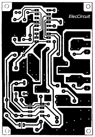
PCB layout
Then put the device in the form in the Components layout. By putting lowermost equipment before. Then gradually by higher equipment respectively. To facilitate the operation.
For the 2 ICs in the circuits should put the socket IC. To protect heat from soldering. Which may cause ICs damage. Both power MOSFET transistors (Q1 and Q2) Before installed with the heat sink. Must insert by a sheet of mica prior to the body of MOSFET short circuit to the heat sink.
And for better cooling efficiency. Should apply silicone cooling pad with mica.
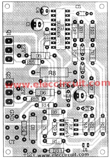
Figure 2
When all the components on the PCB completely. The next step is the wiring to the transformer. And equipment that are outside the PCB.
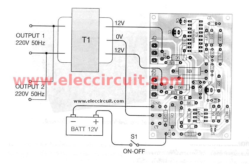
The connection wires on this project
Testing and tuning
The final stage of the project is The functional testing of the machine. It can work normally or not. Beginning Must provide supply +12 volts from the battery to the circuits.
Normal dimmer LED must be on. Then, use the multimeter set range on AC 1000V to measure the output voltage.
If the circuit working correctly measured approximately 220 volts. If not for the lack of print – not Short, Enter not guilty. The circuits to work immediately without any customization.
This project should not be used to test DC voltage 12 volts from the power supply. Because of this power inverters to the power current source is quite high. If using full capacity. Use high current to 10 A.
If the power source can not supply this amount. They will enter to the protection status immediately. Because the voltage falls below 12 volts.
Thus, in the experiment or the actual use should be running on battery power. Which can flow over the general power supply.
For ease of implementation. They should find circuit box containing all and connect wire DC input out. The wire used should be no larger than 4 square millimeters.
Under 500 watts is perfect
The inverter unit is a compact. Suitable for use with appliances that consume a lot of electricity. Such as fluorescent lamps, LCD TV 22 inch or VCD player generally. Should not be brought to the appliances that consume more energy.
Such as irons or an electric stove. Because it makes machine stop to the protection status (without damage).
Bringing this project to implement offsite. Such as to camp overnight. May want to use different appliances. Which would have the power source from the battery of the car.
The batteries in cars are size from 80 to 100 amps per hour. If the battery is full. Will be able to power machine 200-watt inverter for over 8-10 hours.
The battery is weak. Which, if brought to the inverter fluorescent lamp fluorescent Generally, the size (36 watts) can power your car battery with an inverter and all night long. Without having to ignition. Machine cars leave the noisy and oil. Due to concerns that the wakes in the morning to start the car misfire The battery pack is exhausted.
The voltage 220V 50Hz from this inverter Sine Wave signal is not as light as the perfect home. Frequency 50.00Hz and may not fit. There may be some slight error. Therefore, it should not lead to an electrical device. Or tools that require high accuracy. Such as instrumentation. Which may cause these devices. Working correctly.
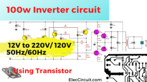
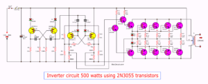
Do you want to modify to 500 watts inverter circuit
OR
Inverter circuit, 12V to 220V at 500W
Caution
the more important reasons are Be careful not Must use very high input voltage than 12 volts. Because of the high pressure, high output voltage as well. This may result in Equipment & Supplies damage were available. But if the car battery is the power source. I do not have to worry about this problem.
Usually, because the battery voltage is 12 to 13.5 volts only. Which voltage of this size can not increase the output voltage to cause harm to any of our electrical equipment. Which voltage output power. Will vary according to the input voltage specified in Table 1.
(loaded use the full power 200 W).
Input battery and AC output voltage
| Input voltage (DCV) | Output voltage (ACV) |
| 11.5V | 182.4V |
| 12V | 194V |
| 12.5V | 205.4V |
| 13V | 214.3V |
| 13.5V | 223.0V |
| 14V | 231.5V |
The parts list
Resistors (All size of 0.25W 1% Unless Specified)
R1: 15K
R2: 22K
R3: 2.7K
R4: 10K
R5: 12K
R6: 4.7K
R7: 47K
R8: 0.01 ohms 5W
R9: 1K (PTC)
R10: 8.2 ohms
R11: 16.9K
R12: 33 ohms
R13, R15: 22 ohms
R14: 18 ohms
R16: 1K
R17: 470 ohms
Capacitors
C1,C2: 220uF 16V, Electrolytic
C3,C7,C9,C10: 0.22uF 50V, Polyester
C4: 1uF 50V, Electrolytic
C5, C6: 0.033uF 50V, Polyester
C8: 2.2uF 50V, Polyester
Semiconductors
D2: 1N4148, 75V 150mA Diodes
D3: 1N4002, 100V 1A Diodes
D4: 18V 1W Zener Diode
D5, D6: BY299, Diodes
IC1: LM393N, Op-amp
IC2: SG3526N, other
Q1, Q2: IRF540, MOSFET Signal Diode
D1: LED, 3 mm
Others
T1: Transformer 220V/12V-0-12V; 200 watts
PCB, metal box, Wire, plug 220V, etc.
You may like these circuits too.

Related Posts

I love electronics. I have been learning about them through creating simple electronic circuits or small projects. And now I am also having my children do the same. Nevertheless, I hope you found the experiences we shared on this site useful and fulfilling.
What about the Transformer making?
Hi Salim, again.
The transformer is normal size 200 watts or 200VA.
Is it a sine wave inverter?
Please kindly inform type of power mosfet
thank you
I like this website electoric
this webside is excellent because in other websides are not directly disply but here detaileld information got it…..so sallute and thanks
Good Day,
If I will add more MOSFET at its output, will it increase it’s capacity? Can I increase this up to 500 watts?
thanks for posting this sg3526 inverter circuit. pls can it be converted to signwave?
I need signwave inverter. can you help me. Umesi.
hey, can you give me a link of a 1K (PTC)resistor or a photo how it looks? I can’t find it to buy.
Good Day,
I just want to ask that is this inverter is capable to charge the battery automatically?and when the power goes dc will it be automatically supply the power?
does inverter increse\multiple\boast power after convertion or does its output depend entirely on the input from the battery i.e the amps and voltage from the battery
Size Kits ?
Dear EC projects , Really it is good help for me how to make the inverter circuit, but give in depth ratings of Transformer & battery.
is there anybody had tested this ckt?
Can u public schematics ?
Hi,Milos
Thanks for your feedback.
Yes I can but please read at “note” because this project have many page.
Hi Admin, May I Use 12v 100Ah lead acid Battery(Which commonly use in home inverter)with this circuit. Please Reply ASAP.. My Circuit is ready I just Want to know about the battery..
Thanks & Best Regards
Anjan Chatterjee
Can I use vero board to make this circuit or in copper clayed board …….how to make it in copper clayed board
Hi, Sam
You can make on normal pcb.
This large size view so clear.
Can I use a 12v 7ah battery for this inverter ………..how long does it gives backup…….
How many amps of transformer can I use for 220v ac
How many amps of transformer you are using to give 220v ac………….and can I use 12v dc 7ah battery……….how many ah is the best
hi sir
am naresh how many amps this transfomer use?
Hi,sam
Thanks for your feedback.
If we need fully watt.
200 watt output = 200 watt input.
12V at input,
so current input about 200/12 = 16A
or use 16A transformer.
Hi,S.Naresh
Yes, You can use 7Ah battery.
If you need full power you need to use 80Ah
for 5-8 hour use.
hello sir i am from pakistan .i am interesting in technical works .i like your circuit diagram .i will try it. please will u guide me ?
sir i need 800 va ups circuit
sir will you please send me its schematic circuit diagram
Hi, asim
Thanks for your feedback.
Please read note: in this article above.
Read all link article about this project.
please sir, can you help me make inverter plane and send it to me here in Nigeria? like 500watt and how much is going to cost me, send me an email for reply thanks
pls sir, i need auto-power change-over circuit diagram
hello sir I need add fuse for protection & also guide me how to prevent overcharging of battery
Is ac i/p for charging the battery is same for ac o/p. plz guide me how to install in wiring
hi,please guide about pure sine wave inverters and short circuits protections
Thanks for this information
Can I get circuit diagram for 12v 150ah battery charger?
Can i use a vero board?
How battery charging?
Pcb making size?
Hi rashid,
Thanks your feedback.
You need to prints with 300 dpi per inch scale.
Hi, multi-amp transformer should be?
Sir, in the above circuit we are supplying 12 v battery to transformer..But how is it possible for the transformer to operate when DC is applied?
Can i useSG3524 instead of SG3526N?
SG3526 is an 18 pin chip where as SG3524 has oly 16 ping. So I gess you cannot.
It is okay if i use 3A transformer?
very very understandable.thanks
plz keep it up
Can i use 5 amps transformer
Sir Can u send me the schematic of this circuit..thanks…
Sir please send me the circuit diagram of the 300 watt lnverter
The website is good. Material is presented in an easy-to-undastand way. However I am having difficulties to download the text. Can you upload a pdf file. Thanks for being so helpful.
Hello Charles Sambani,
Thanks for your visit. I’m glad you liked my website. It’s a very good idea.
You want to read the content of my website in ebook format, right?
At the moment I still don’t know how to do it. According to your needs
However, I am very grateful that you opened my website. And like the content Because every time you read it.
I earn income from advertising. It gave me the funds to keep improving this work.
Have a great day.
Apichet.
To the best of my understanding, SG3536 id discontinnued by ON semy. I think that it is still available from ST Micro electronics. Can SG3525 be used in place of SG3526?
Regards,
Job
Hello Job Thykkoottathil,
I’m sorry, I don’t have any information. However, I respect you. with an effort Have fun creating projects, solving problems step by step.
irf540n 2 for 45am battry pawitci karanna puluwanda