When you need a high-power MOSFET amplifier. For use in applications such as a concert, theater, festivals, etc. This circuit is the most suitable. Both Loudness and durability, that courage to try.
For this MOSFET Amplifier circuit, typically the maximum watt power at load 4Ω equal to 300 watts. or about 200 watts at load 8Ω. Which the watt power very much this level. If you are not satisfied. Also may add a higher power.
Note: I edited the PCB layout to clear view.
For example: Increasing onto 1200 watts with the bridge adapter circuit. Or If will use a folkway that locals they made popularly are connected the output MOSFET transistors in several parallels. To can resist the higher currents. Then connects the speaker that also the several parallel utils the load is very low resistances, some time is internally OHM Now also called as a 1000 watts!
Which would you prefer, you can choose as well.

As Figure 1 is shown the 300watt MOSFET amplifier schematic diagram, a version of our standards.
How does it work
Base on the Figure1, which determine All complementary input form will consist of the differential circuit of two sets, the separate independent, responsible for driving directly both the positive and negative side output.
As it can see that the positive side signal will be entered pass through the resistor R4 to the differential amplifier circuit with two 2SC1775 transistors Q1, Q2, which there are Q3 acts as the constant current source.
The signal is amplified by the driver circuit consist of the Q7(2SA640), Q8(2SA640), Q9(2SA690) to as the signal voltage is high enough to drive the output 2SK1058 MOSFET Q14, Q15, Q16, Q17 for acts as the positive signal to the speaker. (2SJ162 MOSFET Q18, Q19, Q20, Q21 for the negative signal)
The resistors R43, R45, R47, R49 that are at the source pin to help the average current through the MOSFET equal to the function of a circuit more stable.
The capacitors C17, C18, C18, C20 protects the noise oscillator in this. Why we put it as only side MOSFET N Channel. Because normally. The capacitance between Gate-Source of N Channel will lower than P Channel of about 400pF (Normal the P-type will have a value of C=900pF, but N-type = 500pF)
The diodes D16, D17, D18, D19 act as a protection to a gate of MOSFET, do not get too high a voltage driver. It may cause damage through the gate. Typically, the maximum voltage will not exceed 15 volts.
The transistor Q10 is setting a bias voltage value of the circuit. With adjusting the idle current on VR1 for this circuit we should adjust the Idle current to about 80-120 mA.
The total gain of the circuit is determined with feedback circuits R24, R25, R26, C11, C12, and for this circuit the growth rate of about 220 times.
The negative signal will enter to the below side differential circuit consisting of Q4, Q5 has the output signal from Q4 go to the driver circuit Q11, Q12, Q13 to driver power MOSFET works in a negative channel of a signal.
The R51, C23 are used to protect the oscillator in high frequency by connecting the speaker wiring and speaker
The power supply
For this voltage, we use positive/negative 80 volts. We may use a 75 volt one. The features of the circuit are reduced, ostensibly. But lets you select the filter capacitors are quite a lot.

Please try to be to know that was true.
Characteristics of power supply circuit. As shown in Figure 4. The transformer that uses in this project we use a size of 58-0-58 volt 10A provide through the bridge rectifier and the filter capacitor about 22,000uF 100V, or 10,000uF 100V for 2 is connected in parallel instead.
We need to carefully use the transformer. It will help to produce high performance truly.

Let’s build this project
Those who think to build this MOSFET amplifier project. Should have experience in the audio sufficient. This will require careful and skilled in soldering is higher. Otherwise, it throws money to breathtaking. Because the equipment is quite a lot expensive.
– Building start of the main-board. Securely attached by soldering to a point. , Put it in the right position. And A polarized components such as the diode and electrolytic capacitors do not have to be absolute.
– Check the position of the transistors pin, should be accurate as of the circuit. And that same body must be not alternate.
– For transistors Q9,Q13 should correctly the heat sink before installing to the PCB.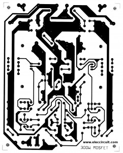
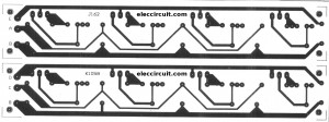
Figure 2 the PCB layout
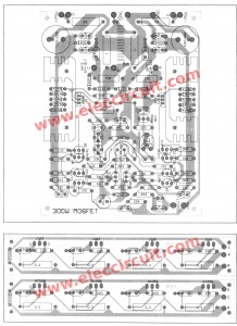
Figure 3 The layout of PCB
-The assembly of the power MOSFET, prohibited, pin S touch the heat sink is strictly prohibited. And for good cooling. We apply silicone between the MOSFET and the heatsink.
This is the reason the copper pin Source and pin drain of the MOSFET current can not get high. Use copper wire number 18, a soldered copper pattern is pressed on it.
Then, connect the cable from the output MOSFET board. Onto the motherboard. Do not switch the switch positions is strictly prohibited. The wires must be large. And not broken or easily broken.
The testing project
When the project is complete. To check the accuracy with the eye again. The previous experimental input voltage to the circuit.
– Using a voltmeter to measure the voltage at the speaker, while Short the input to ground should be zero volts. If it does not show that. circuit malfunction. Immediately turn off the power and check again.
If the voltage is zero. The next step is to adjust the Idle current of the circuit. Using an ammeter. The power of the positive or negative voltage. VR1 adjusts to the current 80-100 mA.
Turn off the power supply to this Mosfet amplifier. Remove the ammeter and the Short Line Input out. Power supply to the circuit again with the input signal to the point. input will be heard from the speakers as you need.
When used with a full load and continuous for a long time. We should install the proper cooling fans to the Power MOSFET. The key is indispensable. Another possibility is speaker protection. Which must use it always with the high-power amplifier. The relay contacts are big as well.
Caution! This project needs to use the speaker protection circuit. Otherwise, your speaker may be damaged.
More MOSFET Amplifiers
- First simple mosfet amplifier circuit by K134+J49
- 100 watt DC servo amplifier circuit by Power MOSFET
- 50w mosfet amplifier circuit OCL using K1058 + J162
- 300 watt MOSFET Power amplifier circuit class G
Related Posts

I love electronics. I have been learning about them through creating simple electronic circuits or small projects. And now I am also having my children do the same. Nevertheless, I hope you found the experiences we shared on this site useful and fulfilling.
The signal output was okey at maximum volume at the speaker but distorts as you reduce, more escipecially soon to reach the minimum volume level. The cct board i’ve built is so clear and accurate.please advise…tel.0782911576 uganda
Good day to you can you please sent the pcb to me so I can build this amplifier. B
Regards
Ioannis stamatopoulos
From Greece.
I’VE LOOKED EQUAVALET FOR MJ21194-MJ5024-MJ21193. COULD YOU TRY TO ADVISE ME ON THAT AND SEND ME MORE AUDIO AMPLIFIER CCT DIARGRM RATING 1000-2500WATTS OF WHICH AT LEAST ARE CHEAP AND SIMPLE [email protected] TEL=0782911576 [uganda ]]
mjl21193 for best eqwalent 2sc1943 & mjl21194 for 2sc5200
Change R31-32 value to 47k (Range between 39-47k)
can u plz tell me the replacement of c3,c12,c13 & c14
i want to buy ready made AUDIO AMPLIFIER
I like the circuit and i can buy it anyway.
The PNP and NPN input reminds me of the Marshall Leach amplifier:
https://users.ece.gatech.edu/mleach/lowtim/
I wish to have such cct with higher power ratings than that! please sent me via email that are not complicated because am an o level student and does understand some beats of this please help me
I buit this amplifer 300>1200 first time but it needs think deeper just call+258 845326274 on fb nelson tsamila/twitter @ntsamila.
Hi, @ntsamila
Thanks for your feedback.
Really, I don’t tested this circuit but this kits that sell long times 30 years many people build them.
I’m sorry that cannot help you.
Hie chayapon why d yo think so bro help me can yo ans on fb /nelson tsamila
A 300>1200w mosfet amplifer i belt it 1yr ago now is still walking its powerful %-)
Dear sir,
How can get this pcbs 300>1200 watt amplifier circuit
Pl send a Quatiton
i want to buy 2000 watt readymade amplifire pl giive address in mail- [email protected]
Respected sir,
This is my hobby to make high power amplifier more than 4500 waat or 7800 watt. So please help me. And provide the circuits diagram by mail
Thanks a lot.
Sir,
I want to 2500watt or 3500watt high power audio amplifier circuit diagram using MOSFET or IGBT. Please help me
Please mail the circuit diagram
i need to this board but how to buy PCb
i liked the circuit ,but you may add some more useful diagram
eti want a asembled board of this amplifire circute 1400w mosfet. how can i get this item iwant only one pc and how can i pay the amount & how much price will come
I want the facing of the n-jfet transistors pls am having problem in the facing
I want to 12volts stearo audio amplifire circut digrame
Sir,
i am planing to build that 300-1200 watts amplifier, but can i add the bass and treble circuit? and how? please send me a details Sir regarding to that matter thank you, [email protected] that’s my email sir i appreciate your response Thank You!
This is a power amplifier circuit. The GAIN of the amplifier BOX is fixed to x20 or x30 ( over the audio range ). You apply the input signal, and the OUTPUT results in the SPEAKER. The input signal is provided by the PRE-AMPLIFIER (aka the pre-AMP). This pre-AMP controls the AMPLITUDE of the input signal that goes to the AMPLIFER. The pre-AMP is where you would introduce a circuit for BASS and TREBLE TONE-CONTROL. In the 1980s, stereo AUDIO equipment was sold as “separates”. A pre-AMP with BASS and TREBLE knobs, and a toggle switch for BASS-boost. Then the stereo output of the pre-AMP was connected to the AMPLIFIER; the amplifier was actually 2 amplifiers: the LEFT and RIGHT AMPLIFIER. – Cesar from Santa Clara, CA
The transistors connection in the pcb is different from that of main circuit diagram,the A968 has a diode in the base but in the pcb layout it not so,pls help me in positioning the transistors
pls can l get complete circuit board (1200w) through post..Nigeria
i have bought kolin 800a then the mosfet power output have been erased and we don’t know the exact number of the mosfet power output . Can we know what is the number of the mosfet power output of kolin 800a ? and Can you help me where can we buy it. Thanks! just email me 🙂
i want to buy a ready made power amplifiers rated 2000watt made of mosfet technology. thank you
Sir can I know what number of MOSFET power transistor of kmp-800a . Thanks !
Thanks for shearing this with us.
Hi all , I made the basic circuit and I ‘ve found some errors:
The diodes D17 – D18 in the circuit diagram are not connected to the output line
The 330 pf capacitor connected to the collector of Q9 is missing on the wiring diagram
The resistor 2.2 k of the feedback network connected with R25 – R26 is omitted in the circuit diagram. This resistor lowers the gain and distortion at low levels , we must review the feedback network.
On the PCB lacks the track that connects the zener diode D2 to + 80V.
The VR1 trimmer does not adjust the quiescent current.
If I can get this to work then I tell you how to do.
Regards.
Hi
Good Day, I want to buy your 300w PCB assy only because I got damaged amplifier. is it possible?
I was thinking to replace the main amplifier. I will the rest parts which still working in good condition. the power supply level is +/- 75 volts. Please advise me if its possible.
How can I have it?
Regards
Rod
Can i use power transistors like 2sc5200 and2sa1943 in place of the power output mosfets?
Thanks.
Please guide me what is the problem in amplifier when one channel is not working after few minutes.
sir i want to make this power amp…can you email me about,where to connect a and b??
good site learning amplifiers
i want to build this,, is it working?
give me the whole file pcb circuit is not
@Marco thanks for warning, this will save many people wasting time on trying to get this thing work
Thank for your support this is great
hi, iwant to buy a complete kit of that 300w to 1200w mosfet amp.pls let me know how to buy tank
I need different informations based on electrical & electronics instruments/ equipments please help me! Thank you!
how can i buy a complete kit of that 300w mosfet,pls contac me ,my number is 09288453460,mail at [email protected]
Soundtop 4000w ampli price list
I want to buy complete kit and power supply please my contact no 9811136136
Can i buy a kit of 300W – 1200W MOSFET Amplifier for professionals only? or the PCBs?
Posso acquistare un kit di 300W – 1200W MOSFET?
I want to buy pcb board. Where I can buy
I want to buy pcb board .where I can buy pcb board …thank you everybody
Pls how can i buy the components online thanks.
what is the Transformer’s current
can you share full kit details
How I can get pcb ,contact me [email protected]
I want to buy pcb board ,contact me vandaocalifornia @gmail.com ,thank you everyone
I want to buy kit pcb contact me vandaocalifornia @gmail.com thank you everybody
i want the whole kit in good working condition. please pink me up at [email protected]
I need full circuite diagram
I wana reddy circut for phonic xp 3000 mosfet replace zone Insart new one zone
Pls sujest
i want buy a kit of 300W – 1200W MOSFET Amplifier for professionals along with power supply unit.
Please inform basic price with term and condition.
Thanks with warm regards.
N K Munda
[email protected]
I have failed to get all the transistors in this circuit
I have built this circuit but failed to operate, smoke on 2sc2238 transistor after 3 second power on…is anyone success can share the experience? Thanks. [email protected]
What is 2SA690? There is no such transistor; I guess its meant to be a 2SA640.
Also it be best if you provided an parts list.
Please I need the full kit of this link me up at good working condition
Doug heere,
I would like to buy the kit and need the full 1200 watt output.
Thanks, [email protected]
Hi Doung,
I am sorry. I do not have a KIT for you.
Your Comment Here…hello guess if you want to build high power 300_1200w amplifier prease send to me your problems its simple starting from 2016 till now is working every day send yr problems here or call +265842831128 or email [email protected]
Its tested?