I like this a dual-LED flasher circuit. Someone calls a blinking LED circuit. They have two LEDs flash alternately.
There are many ways to flash LEDs on and off using transistors. We may call it that Free Running Multivibrator.
It works like Flip Flop that triggers itself repeatedly. It also demonstrates a very important kind of digital logic circuit, the astable multivibrator.
There are 4 circuits ideas for you.
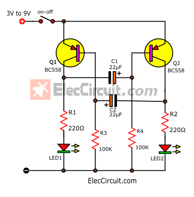
Dual LED flasher circuit using PNP transistor
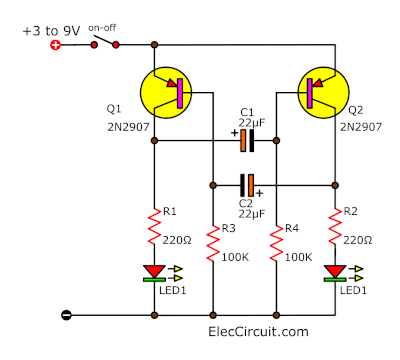
To begin with, see in the circuit below. There are ten components only. I think you do not need to know its principles very very deeply.
I just want to see you use it in an easy way.
Four important things! you should know
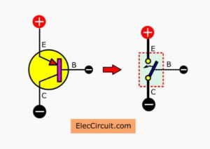
First, Both Q1 and Q2 are general PNP transistors such as 2N3906,2N2907, BC558, etc. They are like switches on-off to drive two LEDs.
Learn: How transistor circuits work
Second, R1 and R2 limit current to LEDs. If you use a 9V battery, you can use up to 1K, 3mm LEDs. In lower resistance will be high current and high lighting.
Third, R3 and R4 make a bias current to the base of transistors to conduct current. They control the gain of amplifiers.
And importantly, they increase the time required to charge capacitors and speed up the discharge of capacitors.
Recommended:
- How 741 Op-Amp Power supply Circuit works
- Basic H-bridge motor driver circuit using bipolar transistor
- How does NE555 timer circuit works | Datasheet | Pinout
Finally, the Flash rate is easily changed simply by changing one, or both, of the timing capacitors C1 and C2. Reducing them will fast the flash rate. When they have different values, one LED will stay on longer than the other.
How does Dual LED flashing light circuit work?
This circuit is so easy, learning how it works is interesting. I will tell you the step of its working. Note: It may incorrect in full academic principles. I hope you understand it easily.
First of all, suppose that Q1 works first. It is a PNP-transistor that works as a switch. We need to feed a polarity voltage. It will work only on the negative voltage.
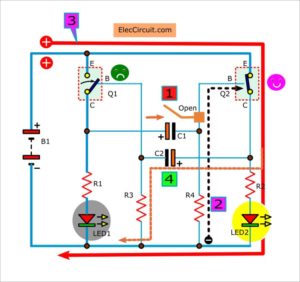
You look at the circuit diagram below.
- First, the positive current from B1-battery comes to the circuit. It is flowing to LED1 through R1 to ground. So, LED1 grows up.
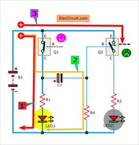
- Second, At the same time, some current also flows to charged C1 through R4 to ground.
- Third, since the voltage across R4 or Base of Q2 is positive. So Q2 does not work, LED2 goes out.
The current comes into C1 slowly until full.
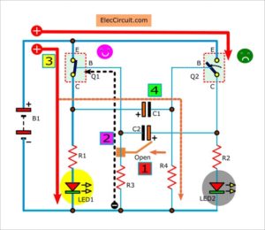
After that, you look a block diagram below.
- First, no current flow through C1. It looks like an opened bridge.
- Second, a negative current from the ground comes to the base of Q2 through R4.
- Third, it makes the Q2 works. So, the current flows to R1, LED to ground. Now, LED2 grows up.
- Fourth, at the same time, some current charges to C2 through R3 slowly. No negative current flows to bias Q1. So it does not work, LED1 goes out.
Next step in Figure below.
- First, at the same C2 is fully charged. So no current through it.
- Second, the negative voltage flows to the base of Q1.
- Third, so Q1 works again. Then, the current flows to LED1 through the collector and emitter, R1 to ground. The LED1 grows up. But LED2 goes out. Why?
- Fourth, since now C1 is discharged to run out. It works like a closed bridge. Then, C2 passes some positive current to R4 instead of the base of Q2. Thus, Q2 does not work, no current through R2 to LED2. LED2 goes out.
This process will work in the loop always follow the principles mentioned above.
Hope friends have fun LED Flasher. This circuit has plenty of fun and practical application.
Keep reading:
- Two LED Flasher using Gate of IC 4011
- How does a transistor circuit works
- 5-30 minuts timer circuit using IC 555
This circuit is working well on a breadboard. below.
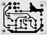
PCB layout
My friend wants a PCB layout of this circuit. So I designed the PCB layout for him and you. It is so easy to builds as Figure below.
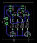
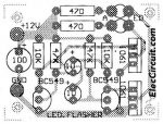
The components layout of Dual LED Flasher using BC556 or BC557 or BC558
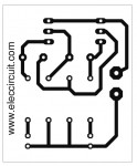
And An actual-size of Single-sided Copper PCB layout.
Credit circuit by Forrest M. Mims III. He is the great Hero(mine) in the electronics world. This circuit is in The getting started in Electronics. I try teaching my children with his books. His book is translated into many languages including mine too. Thanks very much.
Last Update
Peter Notebaert shared: The polarity of C1 and C2 should be reversed. My daughter has retested It has the same effect. Both circuits have the same effect.
Read Also: 1.5V 4 LEDs Flasher circuit using transistors
3V Dual LED flasher using PNP transistors
If you want to use this circuit with 3V battery or 3.7V cell phone battery. You can use this circuit below.
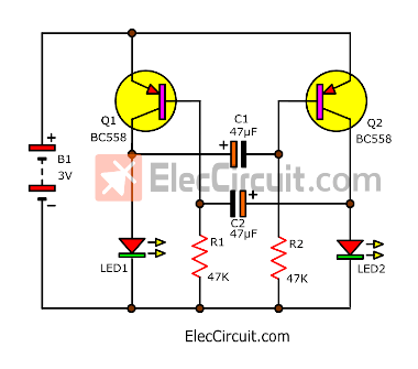
In this case, we use a white LED that requires about a 3V supply. So, it does not need to use the limited current resistor for LEDs.
Next If you have NPN transistor. It also can be made Blinking 2 LED circuit. Both circuits have a few parts. It may be ideas for showing the light of a bicycle or others. Sure, it uses a long battery lasts.
Blinking 2 LED circuit using NPN transistors
I like Blinking 2 LED circuit using NPN transistors. There are many circuits here is one of the blinking circuits. We call it Astable Multivibrator. Often we know it 2 LED Flasher circuit, in this we use PNP transistor.
But now we use 2 NPN transistor. We normally see it in a lot of circuit as oscillators. Both transistor work alternately likes the automatic switches that are alternate working. The collector of Q1 or Q2 makes the frequency signal.
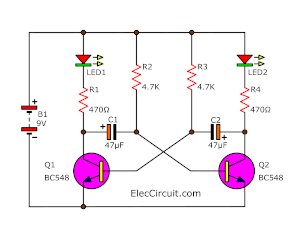
Simple blinking LED circuit diagram
Operation of the circuit
To begin with, suppose that the Q1 run first. Then LED1 should grow more brightly.
It makes the current to flow through LED1, R1, and the collector-emitter of Q1. At the same time, some current will flow through LED2, R4, and to charge into C2 until full. The voltage BE is lower than 0.7V. So Q1 turns off, LED1 goes out.
Next Q2 start working, LED2 also grows more brightly. The C1 begins to charge until full, VBE of Q2 is lower than 0.7V. It turns off, LED2 goes out.
After that Q1 will turn on and LED1 to grow up again. the circuit working will repeat loop in like this.
The bicycle tail light for my son.
The principle of this circuit, I built the bicycle tail light flashing for my son. At first, he was very appreciated. But he embarrassed every time, friends to tease. Because it’s funny.
I used a hot food box because preventing water heat resistant and very economical. And more importantly, it increases the safety of the children. When riding a bicycle in the evening.

3V Blinking LED circuit using transistor
My son wants to build a simple blinking LED. I choose the 3V blinking LED circuit. Because it is so easy. We can assemble all components on a breadboard. And use 3V AA battery.
In the circuit below. We use BC549 transistor and not need Resistor limit current to LEDs.
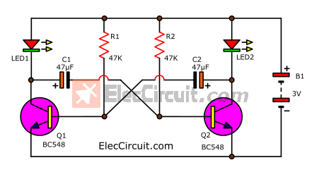
3V Blinking LED circuit diagram.
and He tests it as the video below.
10 LED flasher using multivibrator transistor
This 10 LED flasher is Kind of flashing light circuit which as ideal for use as string light that looks so beautiful. And To add to the atmosphere at night. Or other parties as well. Because it is a circuit that is cheap. The construction is very simple.
You can also adjust the speed of the flashes as well. For flashing that it will flash on – off. Alternately each 5 LED continuously.
Working of LED flasher multivibrator
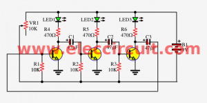
The circuit is a low-frequency oscillator circuit. Which we call that a multivibrator, it uses the dual transistors to work alternating. Each transistor will connect current to one LED set. They have 5 LEDs for 2 set or include are 10 LEDs.
The potentiometer VR = 10K is the speed flashing controller. Which can be slow for the first time about one second. Until quite fast.
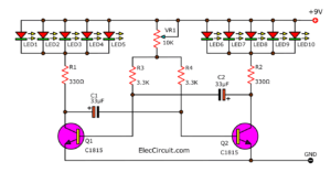
Figure 1 the circuit diagram of 10 LED flasher using multivibrator transistor
The creation and use.
This LED flasher beauty is where to place lamps LED. Here we set the LED alternately in a circle. and Switch bulbs use colors such as green and red. This causes the selected color. Because it is easy to buy colors and bright colors than others.
Assembly, such devices should be R, C, and TR, before, so gradually put the LED. And be careful with the polarity LED. The long leg is the positive leg to turn off the PCB layout.
This circuit is normally set to use the power supply 9V. It can even be used to run low power down to 3V. The brightness is reduced only slightly. The PCB layout can see in Figure 2.
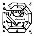
Figure 2 The PCB layout of the 10 LED flasher projects
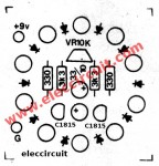
Figure 3 The components of 10 LED flasher using multivibrator transistor
Components list
Q1,Q2: C1815 or C828, 45V 100mA NPN Transistor
C1,C2: 33uF 16V, Electrolytic capacitors
R1,R2: 330 ohms 1/4W 5% resistors
R3,R4: 3.3K 1/4W 5% resistors
LED1-LED10: LED as you needs.
VR1: 10K, potentiometer
Keep reading: ‘LED Chaser circuit’ »
Super 12V Light flasher circuit using 2SC1061
This is Super Blinking Two LEDs circuit. It has high power out to load (12V light bulb), with source voltage form a 12V battery or DC supply, at current 2A up.
We use Astable Multivibrator by transistors and other parts. And two transistors-2SC1061 or TIP41 for drive load up to 10 watts.
This circuit is easy and cheap. We hope you like it.
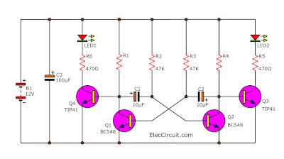
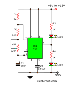
Circuit diagram of Super Blinking Two LEDs
There are a lot of ways to flash dual LEDs ON and OFF. The two transistors are cross-coupled in such a way that the circuit switches back and forth between two states using transistors.
This circuit is one of the most stable of LED flashers. The values in this circuit, two LEDs will alternately flash ON and OFF about once per second.
The Q1, Q2, R1, R2, R3, R4, C1, C2 are a Free running astable multivibrator or Oscillator Generator circuit in a square waveform.
The Flash rate or speed is easily changed simply by changing one, or both of the timing capacitors (C1 and C2).
The Q3, Q4 are power transistors 2SC1061 or TIP31, to drive high up current to dual LEDs includes a series resistor(R5, R6) to limit current.
If we want to use load is the 12V light bulb. We remove R5, R6 and the dual LEDs to use multiple LED light by the circuit.
But you need to use 12V at a current minimum of approximately 0.5A.
Other details see the circuit.
Parts will you needs
Q1, Q2: BC549, 45V 100mA NPN Transistor
Q3, Q4: TIP41 or 2SC1061, 40V 4A NPN Transistor
0.25W Resistors, tolerance: 5%
R1, R4: 10K
R2, R3: 47K
R5, R6: 470
C1, C2: 10µF 25V Electrolytic Capacitors
LED1, LED2, As you like
How to builds
This circuit is small, we can solder them on the perforated PC board to safe money and time. But you can use PCB layout below to good project.
Actual-size of Single-sided Copper PCB layout
Component layout for the PCB
Download This Post as a PDF and all PCB layouts

Keep reading: ‘Fast blinking LED bike light circuit’ »
Related Posts


I love electronics. I have been learning about them through creating simple electronic circuits or small projects. And now I am also having my children do the same. Nevertheless, I hope you found the experiences we shared on this site useful and fulfilling.
thanks.i see your circuit
Hi, farid.
Thanks your comment.
Great Circuits can Be Found here,,MANY THANKS FROM MR.OHM 1970!!!
Merci je suis vraiment ravie de trouvé ce site
Hello Dylan,
You’re welcome.
Thanks
Apichet
Hi, Mr.OHM 1970
Many Thanks too,
Bence 2N2907 li devrenin kondansatörleri ters bağlanmış.
please sir, show the circuit for 24 led dancing light with bc 548 transistors…. am fed up searching for it. please help me sir…
Hello sir. Can i use the 3 volt dc toy motor instead of the led ? I can use it for robot snake. pl reply me on my mail.
Regards
Do you have a schematic for an AM Transmitter. Your web site is #1. Thank You for all your schematics’ You are #1 for all your information. JON.
Can you make a circuit to get a 2 output LED bar / strip 12 volts of the following component list
R 1 K ohm = 1
R 10 K ohm =1
R 330 ohm =2
capasitor 10 nF =1
capasitor 100 nF=1
capasitor electrolit 10 uF/25v = 1
capasitor electrolit 100uF/25v =1
diode 1N4148 = 4
transistor BC547 =1
VR 10 K=1
IC NE555=1
IC CD4017 =1
LED bar/strip =2
help me please
Please sir,can you explan the circuit of 2led flash using transistor which transistor r using is that pnp or npn can u please explan
Send me the explanation and details of transistor pnp or npn to [email protected]
Your caps are in backwards.
It takes a + voltage to turn a pnp transistor off.
Hi Jack Smith,
Thanks for your feed.
Yes, that is right.
Thanks for your reply. I do like this site and will add it to my favorites list.
Hi,
Thanks for your feedback. I will keep my job.
Thank you sir. I will add this site to my favorites list.
Its a very good site and resource for learning electronics circuit design.
Hello Yusuf Abdullahi,
Thanks for your feedback.
About “Dual LED flasher circuit using PNP transistor”
According to me the polarity of your capacitors are wrong.
Suppose transistor Q1 is off and thus trransistor Q2 is on.
That means that the – of condensator C1 is via Q2 (base – emittor) connected to +. At least, the voltage on the – part of the condensator is about V – 0.7
And the + of this condencator C1 is via R1 and LED1 is connected to –
This concencator is immediately charged but with wrong polarity.
So the polarity on condensator C1 is totally wrong and that all the time LED2 is on.
The explanation of the circuit is also wrong according to me.This is what happens:
Suppose LED1 is switching on, then the Q1 is switched on and Q2 is switched off. This means that C2 is now via R2 and LED2 – (since Q2 is off now, so it is not connected to +). The other side of that same capacitor C2 is connected to the base of Q1, which is on which means it is on the + (minus some 0.7 v). This means that this capacitor is now charged almost instantly because there is only a resitor of 220 ohm, the LED2 and Q1. It will have a bit less than 9V in it. You already see now that the drawn polarity is wrong!. Now looking at the other capacitor C1. LED1 is just on. That means that that capacitor is fully charged with almost 9V. On the left (connected to the collector of Q1) -, on the right (connected to the base Q2) + (the other way around as drawn and concluded here just before). This means that the right transistor Q2 gets almost +9V on the base compared to its emitor. That transistor is for sure off because of that. Because the left of that capacitor is now via the left transistor to + and on its right via the 100 kohm resistor R4 to -, it is now being discharged slowly (you may say but now according to you its – is on + and its + is on – via the resistor and that is now wrong polarity and yes, this is correct, but it is still charged with the correct polarity and it is slowly being discharged to the other direction, but it is still charged during a long time with the correct polarity. And yes at a certain moment it begins to charge negative, but only until -0.7 V and very briefly because at that moment the right transistor Q2 switches on. Because it switches on, the other capacitor is put over the left transistor Q1 with its negative charge which makes the left transistor immediately switch off. The result is that our capacitor which has for a brief moment a negative charge of -0.7V immediately gets charged to almost +9V via the right transistor Q2 and LED1 and resistor R1 of 220 ohm. And that almost +9V stays there for a much longer time than the -0.7V.
Hello Peter Notebaert,
First I thank you so much. The polarity of C1 and C2 should be reversed. My daughter has re-tested It has the same effect. Both circuits have the same effect.
You are great, I will use your advice to apply in teaching my children. please tell us more. We are ready to learn it (through fun circuit experiments).
Have a great day.
Apichet and my kids